SPI
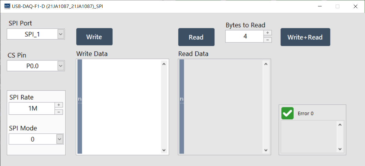
The SPI (Serial Peripheral Interface) panel provides users with SPI serial communication testing. You can set the SPI mode and transmission rate to perform full-duplex communication with peripheral devices.
Supported Products and Ports
This function supports devices equipped with an SPI interface. Please confirm the corresponding port (Port) number according to your device model:
| Product Name | Port |
|---|---|
USB-DAQ-F1-AD | 2 |
USB-DAQ-F1-CD | 2 |
USB-DAQ-F1-D | 1~2 |
USB-DAQ-F1-RD | 2 |
USB-DAQ-F1-TD | 2 |
Parameter Settings
SPI Mode
Four standard SPI modes are supported, determined by the clock polarity (CPOL) and clock phase (CPHA):
| Mode | Clock Polarity (CPOL) | Clock Phase (CPHA) |
|---|---|---|
| 0 | 0 (Idle Low) | 0 (Leading Edge) |
| 1 | 0 (Idle Low) | 1 (Trailing Edge) |
| 2 | 1 (Idle High) | 0 (Leading Edge) |
| 3 | 1 (Idle High) | 1 (Trailing Edge) |
Operation Description
| Button/Parameter | Description |
|---|---|
| SPI Rate | Set the SPI clock rate (maximum 1 MHz). |
| CS Pin | Select the chip select pin (Chip Select) to be used; the specific definition depends on the product specifications. |
| Bytes to Read | Set the length of data to be read (Byte). |
| Write | Send data to the SPI device (Write only). |
| Read | Receive data from the SPI device (Read only). |
| Write+Read | Full-duplex operation: read back data while writing data. |