Servo Drive
The WPC-EDrive-SRV is a single-axis servo motor integrated driver with a network interface. Through the Servo Drive panel, users can intuitively set driver parameters, perform motor auto-tuning procedures, and conduct motion control tests.
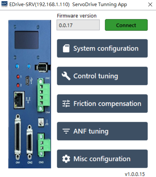
System Configuration
Provides driver configuration file management and firmware update functions.
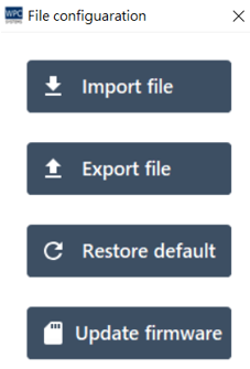
| Button Function | Description |
|---|---|
| Import file | Import a previous driver configuration file (*.ini). |
| Export file | Export and backup the current driver parameters. |
| Restore default | Reset driver parameters to factory default values. |
| Update firmware | Update the firmware (Firmware) inside the driver. |
Note: The update here is for the driver itself; if it is an update for the WPC Device Manager software interface, please go through the general software update process.
Control Tuning
To obtain the best motor control performance, it is recommended to perform the following tuning steps in sequence when installing for the first time or replacing the motor:
Step 1. Select Motor Model
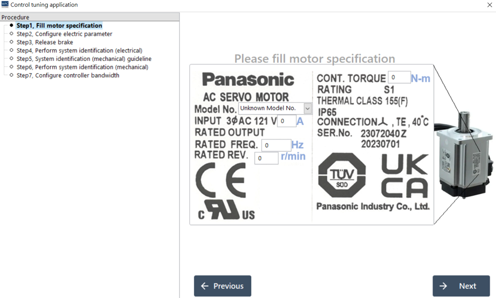
Please select your motor model from the Model No. drop-down menu. The system will automatically fill in the corresponding rated specifications (torque, current, frequency, speed, etc.).
If your model is not in the menu, please manually enter the parameters according to the motor nameplate.
Panasonic series motor models are usually marked on a sticker on the side of the motor.
Step 2. Confirm Electrical Parameters
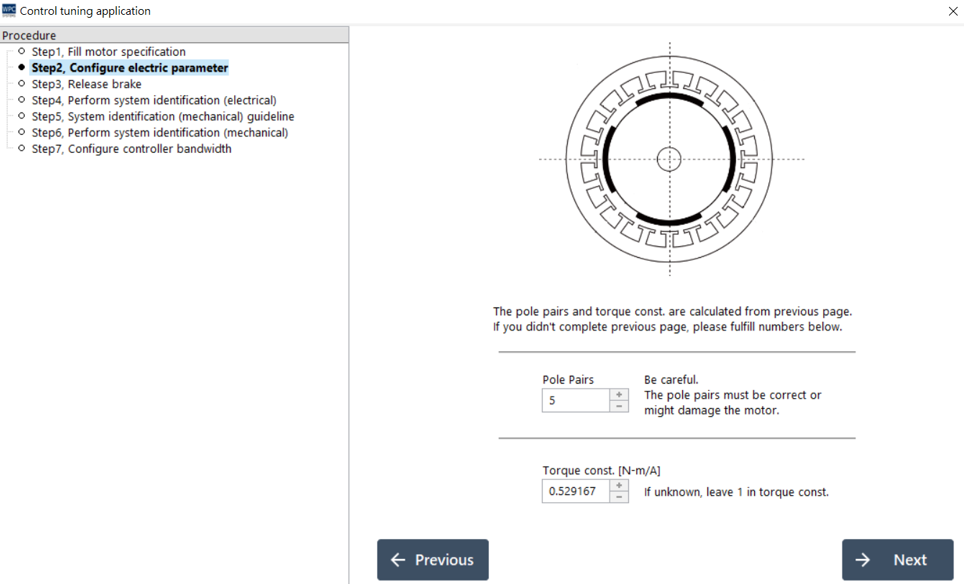
Displays detailed electrical parameters of the motor (such as phase resistance, phase inductance). If the model has been correctly selected in the previous step, no modification is usually needed here; click Next to continue.
Step 3. Release Brake
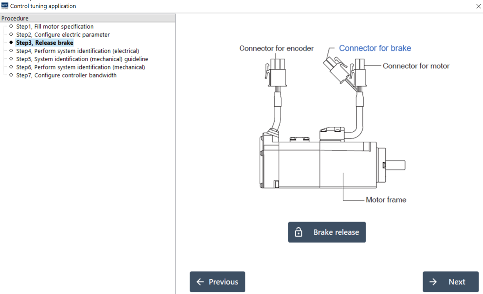
If your motor is equipped with a brake mechanism, please release the brake according to the instructions to ensure that the motor shaft can rotate freely. For detailed wiring, please refer to the WPC-EDrive-SRV Hardware User Manual.
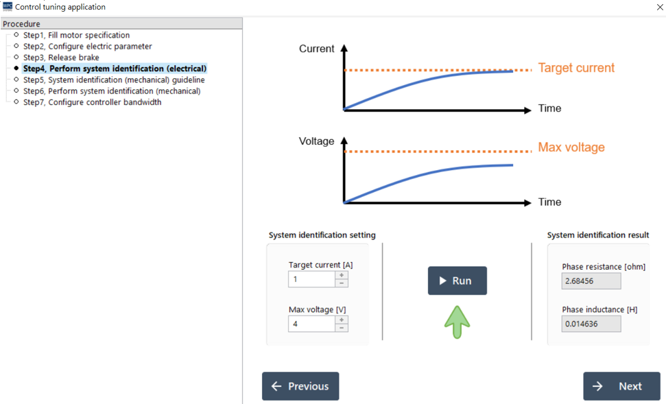
Step 4. System Identification - Electrical Characteristics (Electrical ID)
Automatically measure the actual phase resistance and inductance values of the motor.
- Set Target Current (at least 0.5A recommended).
- Press Run.
- The motor will rotate slightly and lock; after about 2 seconds, a long "beep" sound will be emitted, and the detection status will show a checkmark, indicating success.
Note: The Target Current setting value must not exceed the maximum allowable current of the motor to avoid damaging the motor.
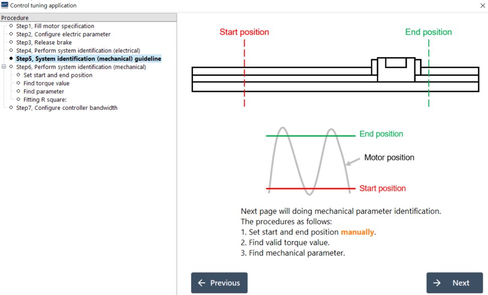
Step 5. System Identification - Mechanical Characteristics Description
This page is a description page; please click Next to continue.
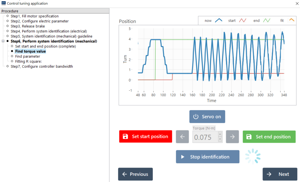
Step 6. System Identification - Perform Mechanical Identification (Mechanical ID)
Automatically measure mechanical parameters such as load inertia and viscosity coefficient.
Operation Steps:
- Press Servo On to excite the motor.
- Manually test and set a Torque value that can make the motor rotate.
- Operate the buttons to move the motor to the Start Position.
- Operate the buttons to move the motor to the End Position. ⚠️ Please ensure there is no mechanical interference within the movement range.
- Press Start identification.
- The motor will test back and forth between the start position and the end position, and automatically adjust the output.
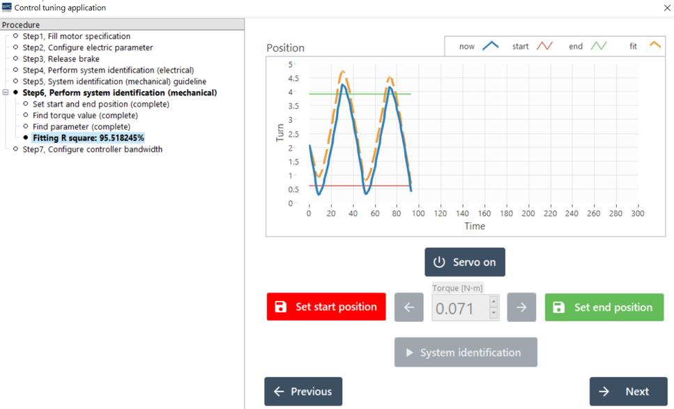
Result Interpretation:
- Fitting Curve (Top Right Chart): The orange dashed line should be close to the blue solid line. If there is a significant drift, it may represent an unbalanced mechanical weight (due to gravity).
- R Square (Data on the Left): Fitting index. If it is greater than 80%, it can be regarded as success; please press Next to continue.
Step 7. Set Controller Bandwidth
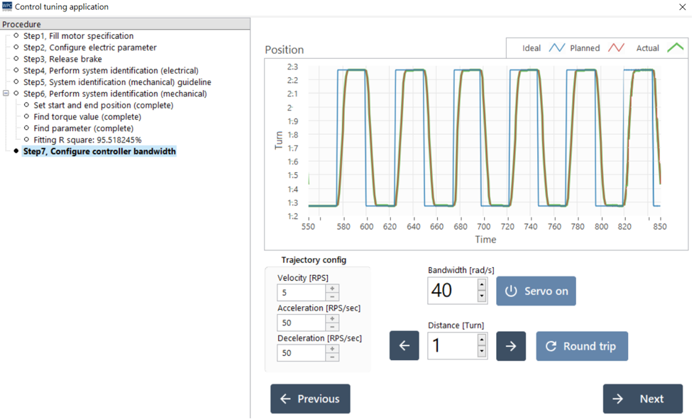
Adjust the response bandwidth (Bandwidth) of the motor.
- Higher Bandwidth: Faster response, stronger rigidity, more accurate positioning.
- Too High Bandwidth: May trigger mechanical resonance and noise.
After setting, press Next, and the system will ask whether to save. Selecting Yes will write the parameters to the driver and backup the configuration file to (WDM path)\data\ServoTune\data\Configs\.
Advanced Functions
Friction Compensation
For short-stroke, high-precision movement requirements, this function can be turned on to eliminate the "Stick-Slip" phenomenon caused by static friction (i.e., hysteresis at startup or pause at turning points).
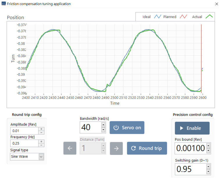
Setting Steps:
- Round Trip Test: Set Amplitude and Frequency, and execute Round trip.
- Enable Compensation: Set Pos bound (recommended as 1/10 of amplitude) and Switching gain (default 0.95).
- Fine-tuning: Enable Enable and observe the error curve. If there is still an impact, you can fine-tune Pos bound or increase the control bandwidth.
Adaptive Notch Filter
Used to suppress mechanical resonance (Resonance). When the motor drives a belt or cantilever structure, if a humming sound of a specific frequency is generated, this function can be used.
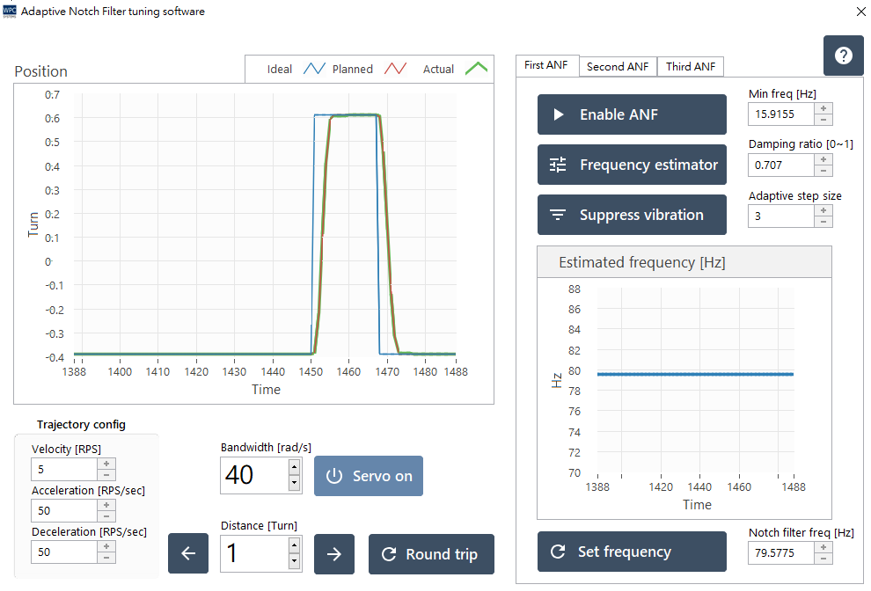
Operation Steps:
- Let the motor perform a round trip movement (Round trip) to induce resonance sounds.
- Click Enable ANF to turn on the filter.
- Click Frequency estimator to start detecting the resonance frequency. Observe the bottom right chart; the frequency should converge to a certain value.
- Click Suppress vibration to execute suppression. The resonance sound should become significantly smaller or disappear.
- If the sound disappears, turn off the estimator and save the settings.
Other Protection Settings
Current Protection
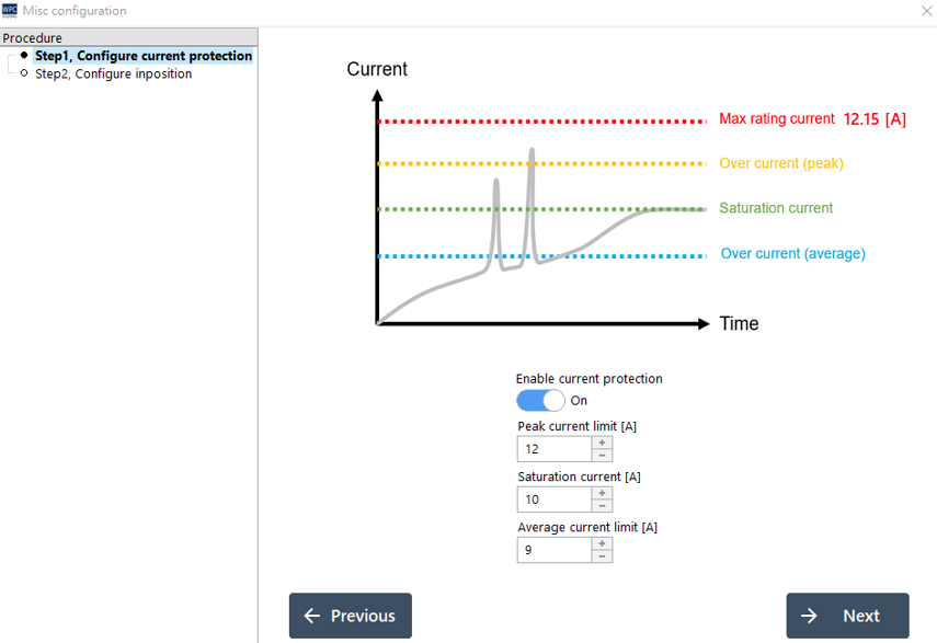
Set the over-current protection mechanism to prevent the motor from burning out due to stall or machine collision.
| Parameter | Description |
|---|---|
| Peak current limit | The allowed maximum instantaneous current value. |
| Continuous current limit | The allowed upper limit of sustained current (average value). |
| Saturation current | The absolute saturation current upper limit output by the driver. |
In-Position
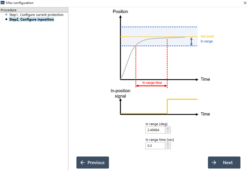
Define the trigger conditions for the "In-Position" signal.
| Parameter | Description |
|---|---|
| In range [deg] | Allowable position error range. |
| In range time [sec] | The duration the position error must stay within the range to be considered truly in position. |