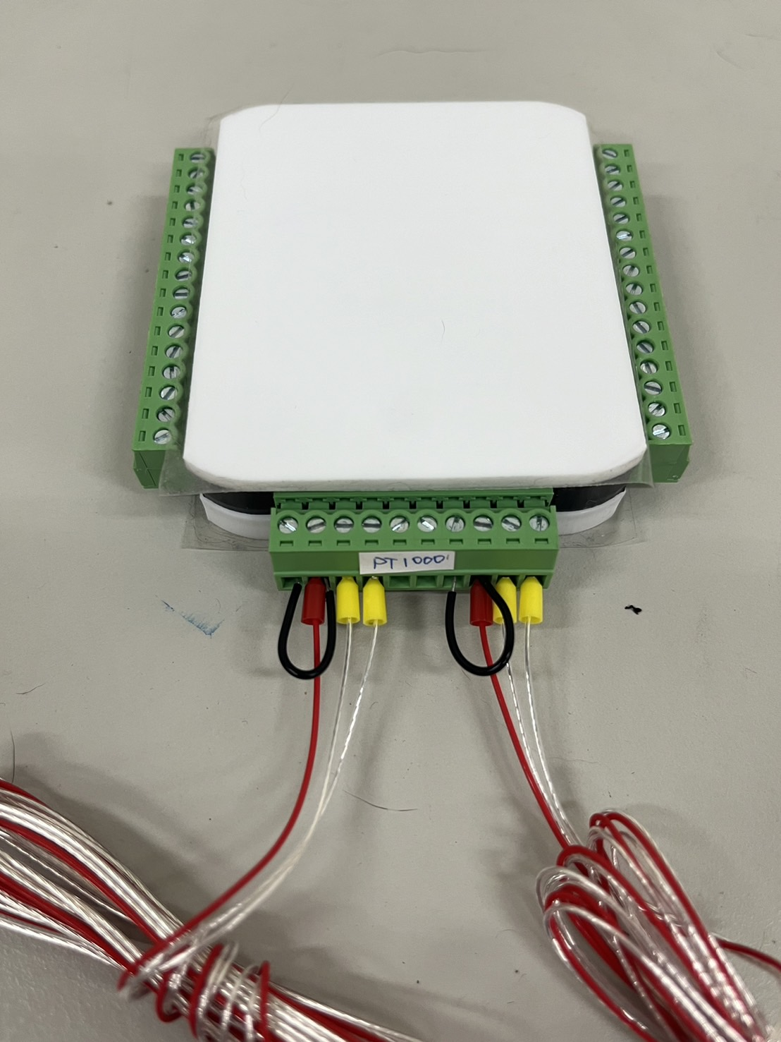
USB-DAQ-RD supports 2-channel PT-100/PT-1000 RTD temperature sensors, providing 15-bit resolution with temperature resolution of up to 0.03125°C and a total accuracy of 0.05%, suitable for high-precision temperature monitoring.
Product Features
- USB 2.0 Full Speed bus-powered
- 21-channel 3.3V Digital I/O (5V tolerant)
- Supports I2C/SPI/UART/PWM/Counter
- 2-channel RTD input
- Supports PT-100 or PT-1000
- Supports Python, C#, and LabVIEW
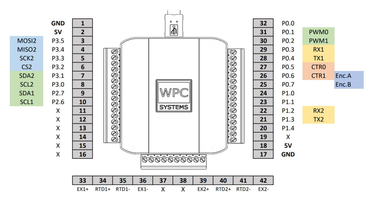
Pinout
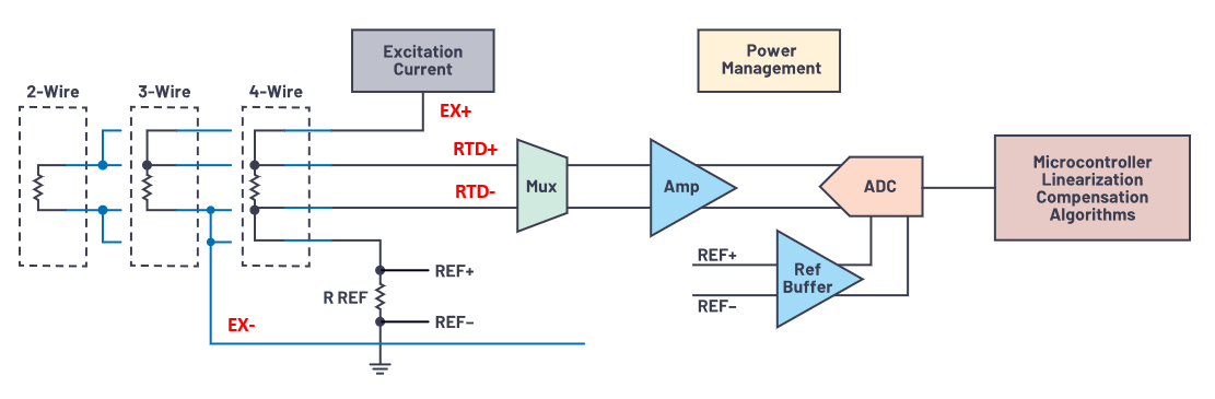
RTD Sensor Wiring Instructions
The following is the equivalent circuit diagram for the RTD inputs of the USB-DAQ-RD. The measurement principle involves using a precision citation current (Excitation Current) of approximately 1~4 mA, which is sent into the RTD sensor via the EX+ and EX- pins. As the current flows through the RTD sensor, a voltage drop occurs across it, which is then measured by an internal amplifier and ADC via the RTD+ and RTD- pins. Therefore, all four pins (EX+, EX-, RTD+, and RTD-) must be used when measuring temperature; none should be left as "No Connection" (Floating).
Wiring instructions for three common types of RTD sensors are as follows:
- For short distances (within 3 meters), the measurement error between these three types of sensors is negligible.
- If the sensor is more than 5 meters from the USB-DAQ-RD, a 4-wire RTD sensor is recommended.
- For 4-wire sensors, refer directly to the 4-wire connection diagram below.
- For 3-wire sensors, an external wire must be used to short RTD- and EX- on one side (or RTD+ and EX+ on the other side).
- For 2-wire sensors, RTD+ must be shorted to EX+, and RTD- must be shorted to EX-.
4-Wire Connection
Product Specifications
| Parameter | Test Condition/Note | Min | Typical | Max | Unit |
|---|
| Input High Voltage | | 3 | 5 | 5.5 | V |
| Input Low Voltage | | -0.5 | 0 | 0.5 | V |
| Input Impedance | | 50k | | | Ω |
Digital Output
| Parameter | Test Condition/Note | Min | Typical | Max | Unit |
|---|
| Output High Voltage | | 3.1 | 3.3 | 3.5 | V |
| Output Low Voltage | | -0.5 | 0 | 0.5 | V |
| Output Current (Source) | | | | 10 | mA |
| Output Current (Sink) | | | | -10 | mA |
| Parameter | Test Condition/Note | Min | Typical | Max | Unit |
|---|
| ADC Resolution | | | 15 | | bit |
| ADC FS Error | | | ±1 | | LSB |
| ADC INL | | | ±1 | | LSB |
| ADC Offset Error | | -3 | | 3 | LSB |
| Rated Temp Res. | Var. by nonlinearity | | 0.03125 | | °C |
| Total Acc. (FS) | | | 0.05% | | % |
| Conversion Time | Var. by mode | | 20 | 66 | ms |
| Voltage Protection | | | ±45 | | V |
| Bias Output Current | | 0.2 | | 5.75 | mA |
| CMRR | | | 90 | | dB |
| 50/60Hz Rejection | Base & Harmonics | | 82 | | dB |
Communication Interfaces
| Parameter | Test Condition/Note | Min | Typical | Max | Unit |
|---|
| UART Baud Rate | | | | 460.8k | bps |
| SPI-1 Trans. Rate | | | | 36M | Hz |
| SPI-2 Trans. Rate | | | | 18M | Hz |
| I2C Trans. Rate | | | | 400k | Hz |