Specific Breakout Board
1. Product Overview
This series of breakout boards is specifically tailored for major brands of servo drivers, aimed at simplifying wiring complexity and enhancing system reliability. Through dedicated SCSI-50P cables, users can achieve Pin-to-Pin direct connection, eliminating tedious single-wire docking and significantly reducing the risk of wiring errors. The European-style terminals on the specific breakout boards are primarily used for connecting limit switches, breakpoints, and capture signals, which are independent of the motor driver and require separate connection.
The breakout boards are applicable to the following major servo motor brands:
- Delta: ASDA-A2 / ASDA-B2
- Panasonic: Minas A4 / A5 / A6
- Yaskawa: SGDV / SGD7
- Mitsubishi: MR-J4 / JE / MR-J2S
2. Supported Model List
| Brand | Model | Breakout Marking | Remarks |
|---|---|---|---|
| Yaskawa | SGDV/SGD7 | S7 | SGDV/SGD7 pinouts are the same |
| Mitsubishi | MR-J4/JE | J4 | J4/JE pinouts are the same |
| Mitsubishi | MR-J2S | J2S | Legacy model, different from J4/JE |
| Panasonic | Minas A4/A5/A6 | A5 | A4/A5/A6 pinouts are the same |
| Delta | ASDA-B2 | B2 | Different pinout from A2 |
| Delta | ASDA-A2 | A2 | Different pinout from B2 |
If your driver model is not listed in the table, WPC provides paid custom breakout board design services. Please feel free to inquire.
3. Functional Configuration and Wiring
3.1 System Architecture
Each motion control card can support two specific breakout boards. A single breakout board can control 2 axes, and a combination of two boards achieves complete 4-axis control.
3.2 Signal Connection
- Servo Drive Signals (CN1 / CN2):
- Connected directly to the driver via SCSI-50P cables.
- Limit and Trigger Signals (T1 / T2 Terminal Blocks):
- Limit Switch: Needs to be connected to T1/T2 terminals (providing 24V power).
- Position Capture/Comparison (Capture/Breakpoint): Provides 5V TTL signal interfaces for synchronized triggering with external devices (e.g., cameras, DAQ).
4. Brand-Specific Wiring Details
4.1 Delta ASDA-B2
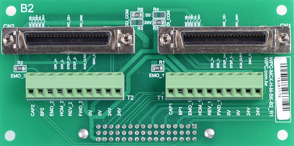
- SCSI-50P connectors (CN1 and CN2) can be connected to Delta ASDA-B2 servo drivers via pin-to-pin SCSI-50P cables.
- European-style terminal blocks (T1 and T2) can be used to connect limit switches, and the 24V power onboard can supply power to these switches.
- Capture and Breakpoint signals are in 5V TTL format, suitable for synchronization with external devices (e.g., cameras, DAQ, etc.).
Factory Defaults
| Signal Type | Logic Setting | Remarks |
|---|---|---|
| Output Signal | Sinking Output | |
| Input Signal | Sourcing Input | |
| EMO (E-Stop) | Enable | Built-in resistor, no external EMO button required |
Jumper Settings
| Function | Setting A (Default) | Setting B |
|---|---|---|
| Output/Input Polarity | Sinking Out / Sourcing In R6/R3 = OR R5/R4 = NC | Sourcing Out / Sinking In R6/R3 = NC R5/R4 = OR |
| EMO Control | EMO Disable (Internal Resistor) R1/R2 = OR | EMO Ext. Control (External) R1/R2 = NC |
4.2 Delta ASDA-A2
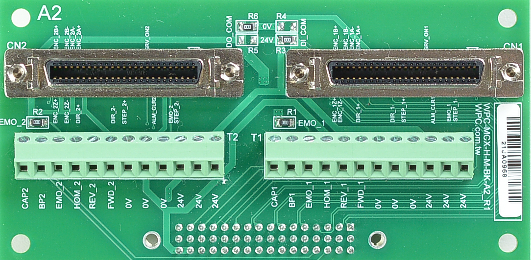
- SCSI-50P connectors (CN1 and CN2) can be connected to Delta ASDA-A2 servo drivers via pin-to-pin SCSI-50P cables.
- European-style terminal blocks (T1 and T2) can be used to connect limit switches, providing 24V power onboard.
- Capture and Breakpoint signals are in 5V TTL format, suitable for synchronization with external devices. The table below shows the factory defaults.
Factory Defaults
| Signal Type | Logic Setting | Remarks |
|---|---|---|
| Output Signal | Sinking Output | |
| Input Signal | Sourcing Input | |
| EMO (E-Stop) | Enable | Built-in resistor, no external EMO button required |
Jumper Settings
| Function | Setting A (Default) | Setting B |
|---|---|---|
| Output/Input Polarity | Sinking Out / Sourcing In R6/R3 = OR R5/R4 = NC | Sourcing Out / Sinking In R6/R3 = NC R5/R4 = OR |
| EMO Control | EMO Disable (Internal Resistor) R1/R2 = OR | EMO Ext. Control (External) R1/R2 = NC |
4.3 Yaskawa SGDV / SGD7
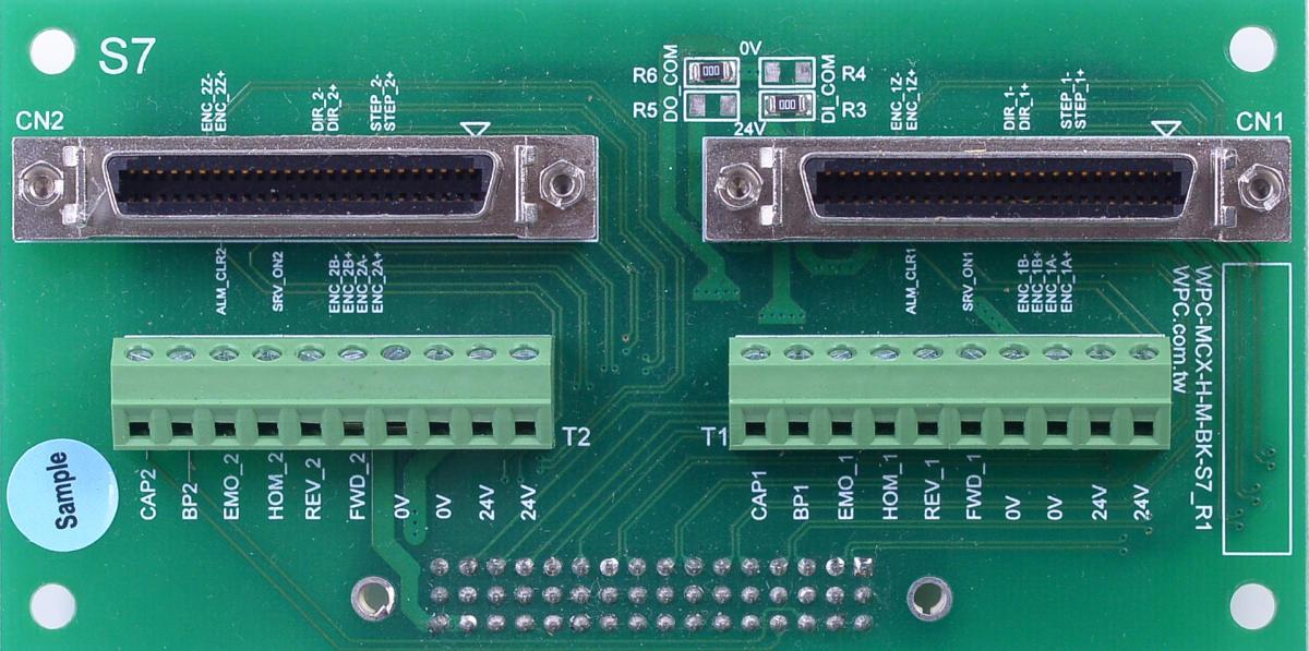
- SCSI-50P connectors (CN1 and CN2) can be connected to Yaskawa SGDV/SGD7 servo drivers via pin-to-pin SCSI-50P cables; the wiring diagrams for both are compatible.
- European-style terminal blocks (T1 and T2) can be used to connect limit switches, providing 24V power onboard.
- Capture and Breakpoint signals are in 5V TTL format, suitable for synchronization with external devices. The table below shows the factory defaults.
Factory Defaults
| Signal Type | Logic Setting | Remarks |
|---|---|---|
| Output Signal | Sinking Output | |
| Input Signal | Sourcing Input | |
| EMO (E-Stop) | Enable | Built-in resistor, no external EMO button required |
4.4 Panasonic Minas A4 / A5 / A6
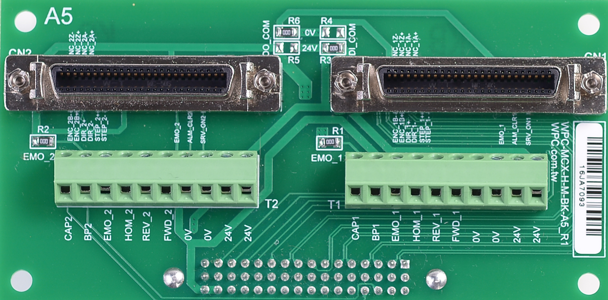
- SCSI-50P connectors (CN1 and CN2) can be connected to Panasonic Minas A4/A5/A6 servo drivers via pin-to-pin SCSI-50P cables.
- European-style terminal blocks (T1 and T2) can be used to connect limit switches, providing 24V power onboard.
- Capture and Breakpoint signals are in 5V TTL format, suitable for synchronization with external devices. The table below shows the factory defaults.
Factory Defaults
| Signal Type | Logic Setting | Remarks |
|---|---|---|
| Output Signal | Sinking Output | |
| Input Signal | Sourcing Input | |
| EMO (E-Stop) | Enable | Built-in resistor, no external EMO button required |
Jumper Settings
| Function | Setting A (Default) | Setting B |
|---|---|---|
| Output/Input Polarity | Sinking Out / Sourcing In R6/R3 = OR R5/R4 = NC | Sourcing Out / Sinking In R6/R3 = NC R5/R4 = OR |
| EMO Control | EMO Disable (Internal Resistor) R1/R2 = OR | EMO Ext. Control (External) R1/R2 = NC |
4.5 Mitsubishi MR-J4 / JE
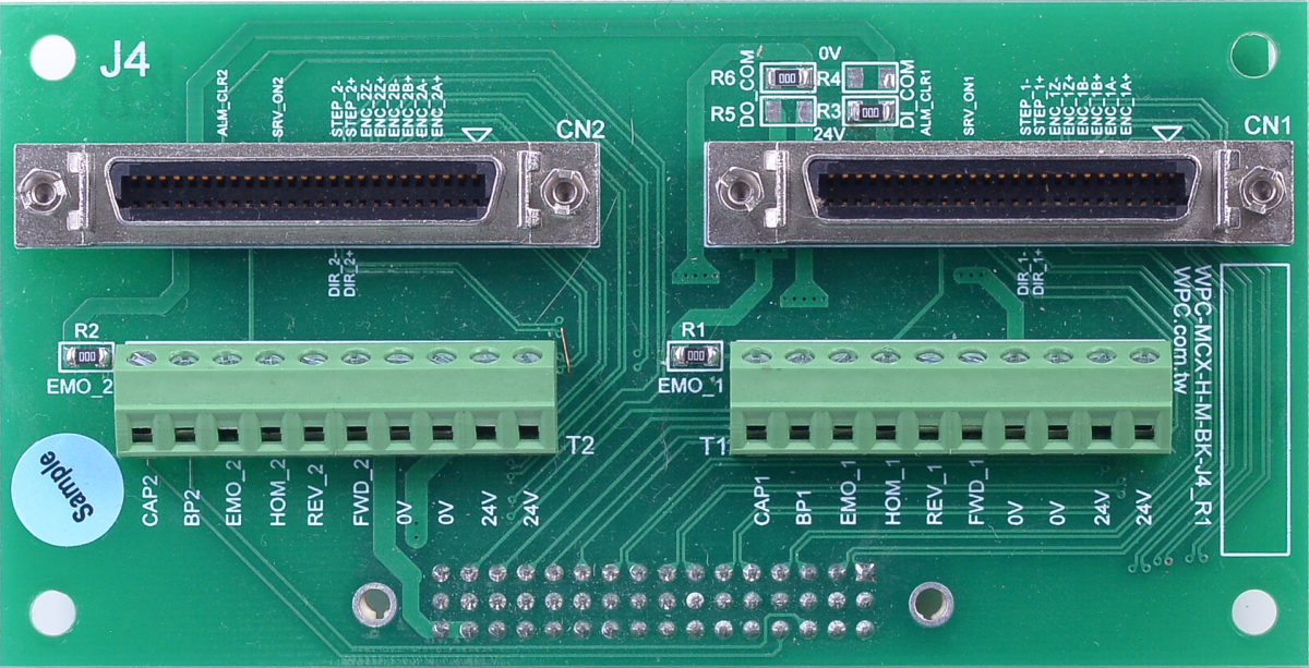
- SCSI-50P connectors (CN1 and CN2) can be connected to Mitsubishi MR-J4/JE servo drivers via pin-to-pin SCSI-50P cables.
- European-style terminal blocks (T1 and T2) can be used to connect limit switches, providing 24V power onboard.
- Capture and Breakpoint signals are in 5V TTL format, suitable for synchronization with external devices. The table below shows the factory defaults.
Factory Defaults
| Signal Type | Logic Setting | Remarks |
|---|---|---|
| Output Signal | Sinking Output | |
| Input Signal | Sourcing Input | |
| EMO (E-Stop) | Enable | Built-in resistor, no external EMO button required |
4.6 Mitsubishi MR-J2S

- SCSI-20P connectors (CN1A, CN1AB, CN2A, and CN2B) can be connected to Mitsubishi MR-J2S servo drivers via pin-to-pin SCSI-50P cables (Note: check specific cable compatibility).
- European-style terminal blocks (T1 and T2) can be used to connect limit switches, providing 24V power onboard.
- Capture and Breakpoint signals are in 5V TTL format, suitable for synchronization with external devices.
Factory Defaults
| Signal Type | Logic Setting | Remarks |
|---|---|---|
| Output Signal | Sinking Output | |
| Input Signal | Sourcing Input | |
| EMO (E-Stop) | Enable | Built-in resistor, no external EMO button required |
Jumper Settings
| Function | Setting A (Default) | Setting B |
|---|---|---|
| Output/Input Polarity | Sinking Out / Sourcing In R6/R3 = OR R5/R4 = NC | Sourcing Out / Sinking In R6/R3 = NC R5/R4 = OR |
| EMO Control | EMO Disable (Internal Resistor) R1/R2 = OR | EMO Ext. Control (External) R1/R2 = NC |