Appearance and Hardware Configuration
Appearance Description
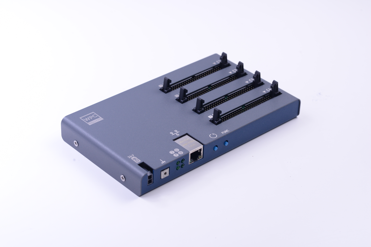
In order from top to bottom:
- C1 (Slot C1): 24ch 3.3V DIO
- C2 (Slot C2): 24ch 3.3V DIO
- C3 (Slot C3): 24ch 3.3V DIO
- C4 (Slot C4): 24ch 3.3V DIO
Interface Description
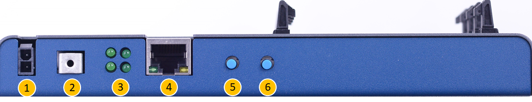
In order from left to right:
- 24V DC Power Input
- Protective Earth (PE)
- LED Status Indicators
- 10/100M Ethernet Port
- Reset Button
- FUNC Button (next to Reset)
LED Indicator Definition
| Position | Name | Behavior Description |
|---|---|---|
| Top Left | Power | • Solid on: Power is on. |
| Top Right | Bootloader | • Blinks twice: Bootloader initialization successful on startup. • Solid on: Bootloader is running. |
| Bottom Left | Status | • Blinks twice: Main program initialization successful on startup. • Solid on: System is running. • Periodic blinking: Error occurred. |
| Bottom Right | OS | • Blinks at ~4 Hz: Ethernet cable connected. • Blinks at ~2 Hz: Ethernet cable not connected. • Off: OS stopped. |
Button Functions
| Button | Function Description |
|---|---|
| Reset | • Short press: Restart STEM. • Press with FUNC: Restart and enter Bootloader mode. |
| FUNC | • Long press for 3s: Reset IP to default 192.168.1.110. |