General Breakout Board
1. Product Overview
This general breakout board is specifically designed for motion control modules, featuring standard European-style terminal block interfaces. Its purpose is to provide high wiring flexibility by pulling out all control signals, allowing developers to freely connect to the vast majority of stepper motor and servo motor drivers on the market.
2. Hardware and Application
2.1 Applicable Scenarios
- Multi-brand Driver Integration: When a system needs to mix different brands of drivers.
- Custom Wiring: When it's necessary to connect motor drivers with special specifications or non-standard pinouts.
- Prototyping: When frequent adjustment of wiring definitions is required during the validation phase.
2.2 Terminal Configuration
The breakout board is equipped with four main sets of European-style terminal blocks, partitioned according to signal characteristics:
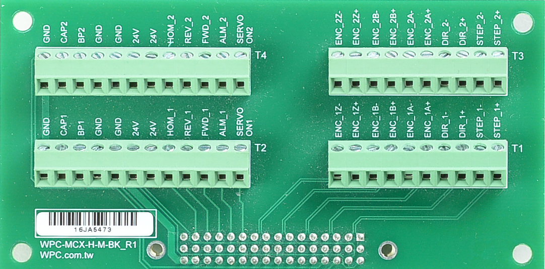
- T1 / T3 Terminal Blocks (High-Speed Signal Area):
- Responsible for handling motor Pulse Output and Encoder Input.
- T1 corresponds to Axis 1; T3 corresponds to Axis 2.
- T2 / T4 Terminal Blocks (I/O Control Area):
- Responsible for handling I/O signals such as Servo On/Alarm and Limit/Home Sensor.
- T2 corresponds to Axis 3; T4 corresponds to Axis 4.
3. Pin Definition and Signal Description
3.1 T1/T3 Terminal Blocks (High-Speed Signals)
This section provides the high-speed differential signals required for motor control.
- Differential Output: Transmits STEP/DIR or CW/CCW pulse commands to the driver.
- Differential Input: Receives A/B/Z quadrature encoder signals from the motor.
- Note: If the Z-phase homing function (Find INDEX) is not used, ENC_Z can be left disconnected.
T1/T3 Signal Table
| Pin# | Name | Level | Type | Dir | Description |
|---|---|---|---|---|---|
| 1 | Step+ | 5V | Differential | Out | Step/Pulse/CW output signal |
| 2 | Step- | 5V | Differential | Out | Step/Pulse/CW output signal |
| 3 | Dir+ | 5V | Differential | Out | Direction/CCW output signal |
| 4 | Dir- | 5V | Differential | Out | Direction/CCW output signal |
| 5 | Enc_A+ | 5V | Differential | In | Encoder Phase A+ |
| 6 | Enc_A- | 5V | Differential | In | Encoder Phase A- |
| 7 | Enc_B+ | 5V | Differential | In | Encoder Phase B+ |
| 8 | Enc_B- | 5V | Differential | In | Encoder Phase B- |
| 9 | Enc_Z+ | 5V | Differential | In | Encoder Phase Z+ |
| 10 | Enc_Z- | 5V | Differential | In | Encoder Phase Z- |
3.2 T2/T4 Terminal Blocks (I/O Control)
This section integrates various switch and trigger signals required for motion control.
- Open Collector Output: Servo On and Alarm Clear, suitable for controlling driver states.
- Opto-coupled Input: Forward (Positive limit), Reverse (Negative limit), Home (Origin). This section supports 24V voltage, facilitating interfacing with industrial sensors.
- TTL Signals (5V):
- Breakpoint (BP): Position comparison output (Trigger Out).
- Capture (CAP): Position capture input (Trigger In).
BP (Breakpoint) and CAP (Capture) are 5V TTL signals. Connecting 24V voltage to them is strictly prohibited. Accidental connection to 24V signals (e.g., miswired to a 24V limit switch loop) will cause immediate damage to the axis card circuit.
T2/T4 Signal Table
| Pin# | Name | Level | Type | Dir | Description |
|---|---|---|---|---|---|
| 1 | Servo on | 24V | Open-collector | Out | Servo on output signal / inhibit out |
| 2 | ALM | 24V | Open-collector | Out | Alarm clear output signal |
| 3 | FWD | 24V | Optocoupler | In | Forward limit switch input signal |
| 4 | REV | 24V | Optocoupler | In | Reverse limit switch input signal |
| 5 | HOME | 24V | Optocoupler | In | Home limit switch input signal |
| 6 | 24V | 24V | Power | Out | Power output for limit switch |
| 7 | 24V | 24V | Power | Out | Power output for limit switch |
| 8 | GND | Power | Out/Ref | Power output for limit switch /Signal reference | |
| 9 | GND | Power | Out/Ref | Power output for limit switch /Signal reference | |
| 10 | BP | 5V | Single-ended | Out | Break-point output signal |
| 11 | CAP | 5V | Single-ended | In | Capture input signal |
| 12 | GND | Power | Out/Ref | Signal reference for BP / CAP |