Common Limit Switch Wiring
This chapter uses industry-standard photoelectric switches (such as OMRON EE-SX67x series) as an example to explain the wiring modes and safety configuration recommendations for limit switches.
1. Wiring Mode Description
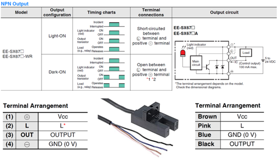
Photoelectric switches typically offer two operation modes, the selection of which depends on the wiring of the L Terminal:
1.1 Light-ON Mode (Active-HIGH)
- Setting: L Terminal left floating (open).
- Operation Logic:
- When light is blocked (object detected): Output is OFF (High Impedance / High Logic).
- When light enters (no obstruction): Output is ON (Low Logic).
1.2 Dark-ON Mode (Active-LOW)
- Setting: L Terminal shorted to VCC (brown wire).
- Operation Logic:
- When light is blocked (object detected): Output is ON (Low Logic).
- When light enters (no obstruction): Output is OFF (High Impedance / High Logic).
2. Safety Recommendations
In industrial automation applications, it is strongly recommended to use Dark-ON mode as the standard configuration for limit switches.
Why choose Dark-ON?
This mode constitutes a "Fail-Safe" mechanism.
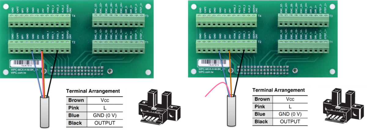
Recommended Safety Configuration
WPC recommends that users set the limit switch to Dark-ON mode (as shown on the right side of the figure above, shorting L and VCC).
- Reasoning: In this mode, if a broken wire or poor contact occurs, the axis card input will detect a triggered limit signal state.
- Protection Mechanism: When the system determines that a limit has been triggered, the axis card will prohibit the motor from moving towards that limit. Although this will cause the machine to stop temporarily, it effectively avoids crashes caused by limit switch failure, ensuring the safety of equipment and personnel.