Dimensions and Installation
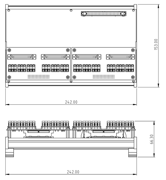
1. Dimensions
The module features a standard DIN rail mounting design with a compact industrial-grade form factor.
1.1 Interface Layout
- Power Input (CN3): 2-pin European-style terminal on the top left, input voltage 24VDC.
- System Bus (CN4): IDC 50-pin connector on the top right, used to connect to GECO or STEM controllers.
- Breakout Connector (CN1): DIN 41612 48-pin connector at the bottom, used to connect to motion control breakout boards.
1.2 Installation Notes
Before connecting the motor driver, please make sure to follow these steps:
- Breakout Board Assembly: Combine the main axis card with the selected breakout board (general/specific) through the DIN 41612 connector at the bottom.
- Mounting:
- First, fix the DIN Rail Clip to the back of the axis card.
- Mount the assembled module onto a standard 35mm DIN rail.
Clearances
- Height Clearance: The DIN rail clip will raise the module by approximately 7.4 mm.
- Overhead Space: It is recommended to reserve at least 82.36 mm of space above the DIN rail to accommodate the bending radius of the SCSI cable and avoid excessive stress on the wires.
2. Power Connection
This module requires an external 24VDC power supply to drive the internal circuits and isolation interfaces.

2.1 Wiring Instructions
- Please use the 2-pin European-style terminal on the top left for wiring.
- If using a non-WPC original power supply, please use a multimeter to verify the polarity.
Polarity Check
Reverse connection of the power supply is strictly prohibited! Before inserting the power terminal, always use a multimeter to re-confirm the polarity of 24V and GND. Reverse connection will cause permanent damage to the module circuit and is not covered by the warranty.