Servo Motor Wiring Examples
1. Control Mode Description
Servo motor drivers typically support multiple control modes, including:
- Position Control Mode: Controls position via pulse commands.
- Speed Control Mode: Controls rotational speed via analog voltage or commands.
- Torque Control Mode: Controls output torque via analog voltage.
Since Emotion is a pulse-train command type motion control card, it only supports the "Position Control Mode" of servo drivers.
Speed Control
Although the wiring must use position mode, users can still achieve precise Velocity Mode control by changing the pulse transmission frequency via software.
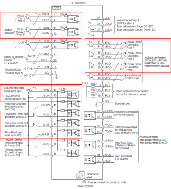
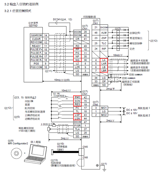
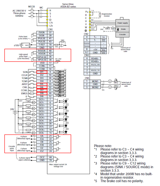
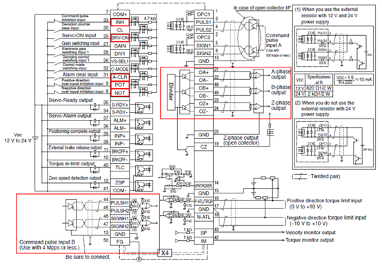
2. Wiring Diagrams by Brand
The following are standard wiring examples for major brands of servo drivers. The red boxes in the diagrams highlight the critical I/O signal points that must be connected to the axis card.
Applying Settings
After changing driver parameter settings or wiring, be sure to power cycle the driver to ensure the settings take effect.
2.1 Mitsubishi MR-J4 / JE
2.2 Delta ASDA-B2
2.3 Panasonic Minas A4 / A5 / A6
2.4 Yaskawa SGDV / SGD7