1ch Programmable Gain Amplifier
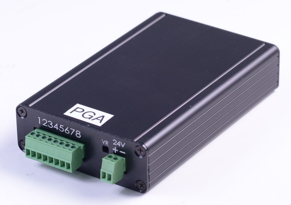
The WPC 1ch Programmable Gain Amplifier (PGA) is a signal amplification front-end module with programmable gain capabilities. This product is designed for application scenarios requiring dynamic adjustment of amplification factors, effectively handling input signals of different amplitudes and converting them into high-quality differential output signals.
Key Features
- Programmable Gain Control: Supports a wide gain range from 0.125 to 128, switched precisely via 4-bit (D3~D0) digital signals.
- Excellent Common-Mode Rejection: Features CMRR up to 140dB, effectively eliminating environmental noise interference.
- High-Safety Isolation Design: Provides channel-to-ground isolation protection, ensuring the safety of the back-end measurement system.
- Built-in Filters: Includes built-in EMI filters and low-pass filters with a bandwidth of 9KHz, ensuring signal purity.
- Precision Offset Adjustment: Equipped with an adjustable resistor (VR) for convenient zero-point offset correction.
Product Specifications and Features
The WPC 1ch PGA provides high-precision and flexible signal amplification. Its main specifications are as follows:
- Power Input: 24 VDC
- Programmable Gain: 0.125 to 128 (controlled via D3~D0)
- Input Voltage Range: ±10 V (Single-ended)
- Output Voltage Range: ±10 V (Differential)
- Bandwidth: 9 KHz
- Common-Mode Rejection Ratio (CMRR): > 140 dB
- Isolation Design: Channel-to-GND isolation
- Zero-point Adjustment: Offset can be adjusted via the built-in VR
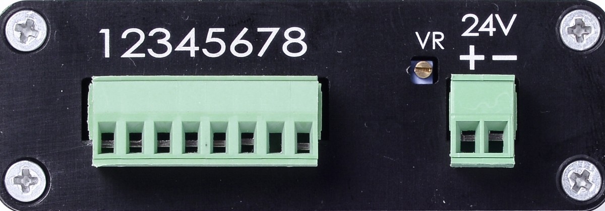
Pinout and Hardware Interface
Below are the detailed pinout and power configuration instructions for the WPC 1ch PGA:
| Pin Number | Name | Function Description |
|---|---|---|
| 1 | Input+ | Signal Input (Pos.) |
| 2 | Input- | Signal Input (Neg.) |
| 3 | D3 | Gain control bit 0 |
| 4 | D2 | Gain control bit 1 |
| 5 | D1 | Gain control bit 2 |
| 6 | D0 | Gain control bit 3 |
| 7 | GND | Digital/Signal Ground |
| 8 | Output | Signal Output |
| VR | Offset Tuning | Zero-point offset adjustment resistor |
| 24V+ | 24V | Positive Power Input |
| 24V- | 0V | Negative Power Input |
note
Gain control inputs (D3~D0) support 3.3V / 5V logic levels.
Gain Control Table
| D3 D2 D1 D0 | Gain |
|---|---|
| 0 0 0 0 | 0.125 |
| 0 0 0 1 | 0.25 |
| 0 0 1 0 | 0.5 |
| 0 0 1 1 | 1 |
| 0 1 0 0 | 2 |
| 0 1 0 1 | 4 |
| 0 1 1 0 | 8 |
| 0 1 1 1 | 16 |
| 1 0 0 0 | 32 |
| 1 0 0 1 | 64 |
| 1 0 1 0 | 128 |
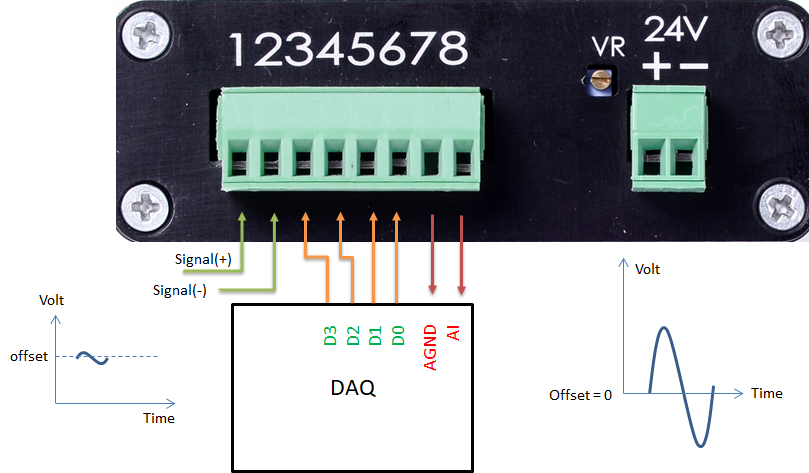
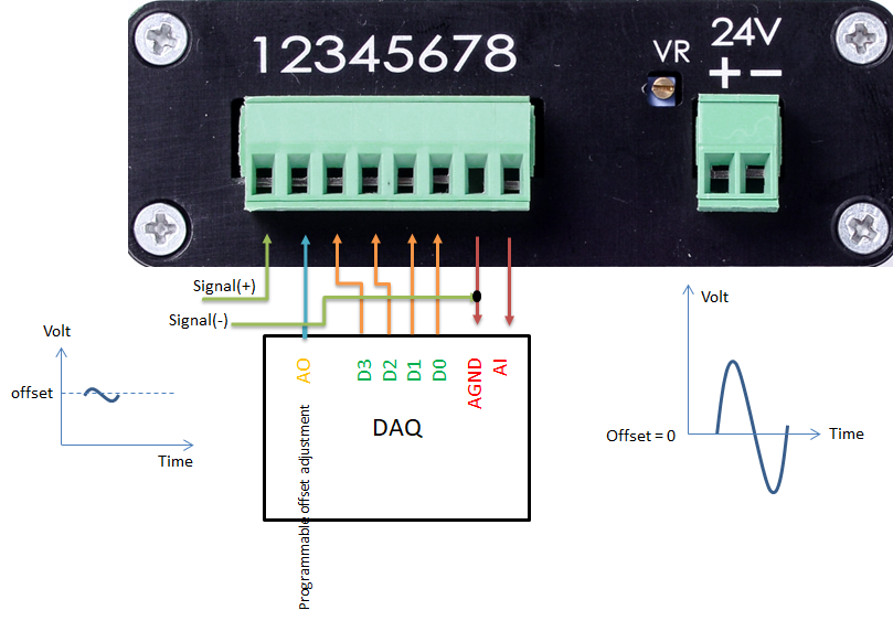
System Connection and Applications
The figures below show typical connection examples for the WPC 1ch PGA in a system.
Connection Example 1
Connection Example 2
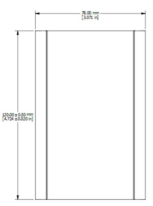
Dimensional Drawing