1ch Load Cell Amplifier
The WPC Load Cell Amplifier (LCA) is a signal processing front-end module specifically designed for load cell measurements. It accurately amplifies the minute voltage signals (typically in the mV range) output by load cells into standard voltage signals, enabling users to perform high-quality mechanical measurements through general-purpose analog input channels.
Key Features
- High-Ratio Precision Amplification: Provides a fixed 1000x gain (Gain), ensuring that minute signals can be captured clearly.
- Stable Excitation Voltage: Built-in 5V excitation voltage (Excitation voltage), capable of directly driving external bridge sensors.
- High-Bandwidth Measurement: Bandwidth up to 9KHz, suitable for rapid mechanical changes and impact measurements.
- Ultra-Low Noise Performance: Noise peak-to-peak value (Vp-p) approx. 10mV, and root mean square (Vrms) less than 2mV, providing clean signal output.
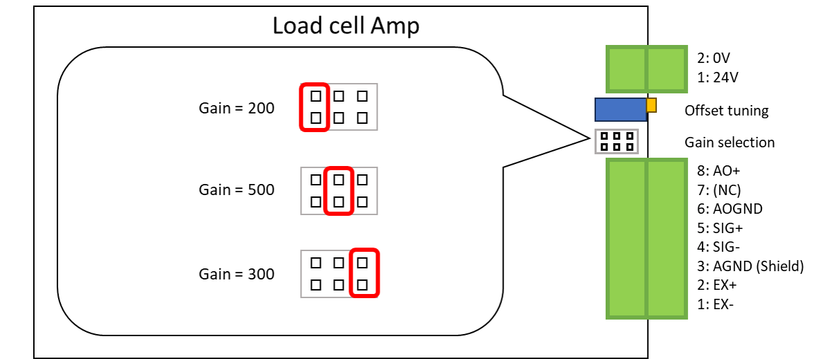
- Precision Zero-Point Tuning: Equipped with an adjustable resistor (VR) for convenient zero-point offset (Offset) compensation.
Product Specifications and Features
The WPC LCA provides outstanding performance for load cell applications. Its main specifications are as follows:
- Power Input: 24 VDC
- Gain: 1000
- Bandwidth: 9 KHz
- Excitation Voltage: 5 V
- Noise Level: Vp-p ≈ 10 mV, Vrms < 2 mV
- Output Range: ±10 V (Differential output recommended)
- Type: External bridge amplifier (External bridge, w/o built-in bridge)
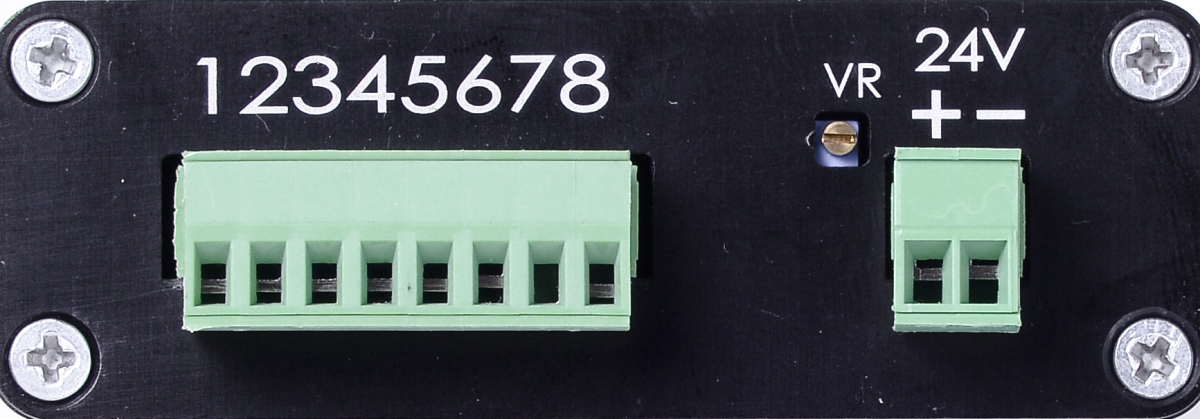
Pinout and Hardware Interface
Below is the detailed pinout configuration for the WPC LCA:
| Pin Number | Label | Direction | Function Description |
|---|---|---|---|
| 1 | Bias- | EX- | Excitation Voltage Negative |
| 2 | Bias+ | EX+ | Excitation Voltage Positive (5V) |
| 3 | GND | AGND | Analog Ground (Isolated design) |
| 4 | IN- | SIG- | Signal Input Negative |
| 5 | IN+ | SIG+ | Signal Input Positive |
| 6 | Out- | AO- | Signal Output Negative (Differential connection recommended) |
| 7 | - | - | Not Defined |
| 8 | Out+ | AO+ | Signal Output Positive (Differential connection recommended) |
| VR | Offset | - | Offset adjustment resistor (Clockwise to increase offset) |
| 24V+ | 24V | - | Positive Power Input |
| 24V- | 0V | - | Negative Power Input |
Gain Selection
System Connection and Applications
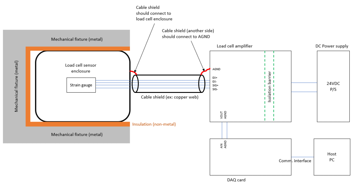
Connection Diagram
The figure below shows the connection method between the LCA and a typical load cell. Please note the correspondence between the excitation power and signal input.

Grounding & Shielding
To ensure measurement precision and reduce electromagnetic interference, it is recommended to use shielded cables for connections and ground the shield layer at a single point. Also, ensure that the module's AGND is consistent with the ground reference level of the measurement equipment.
Advanced Features and Test Results
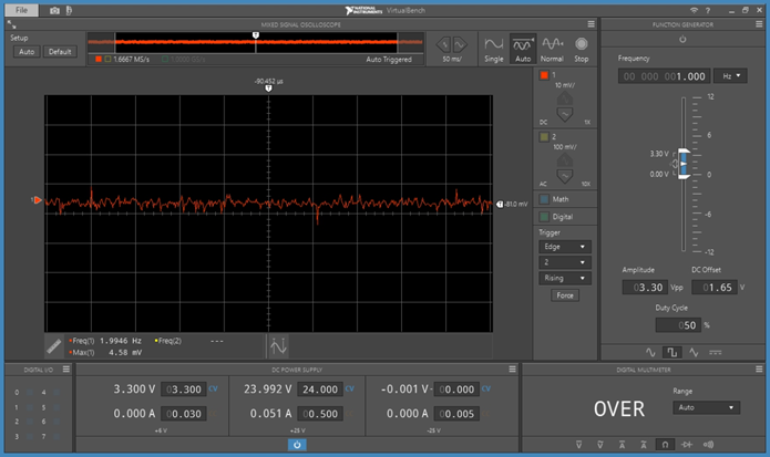
Noise Level
With a time axis of 50ms/div and a range setting of 10mV/div, the base noise of the LCA is approximately between 5~10 mV.
Correlation

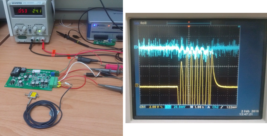
Simple Test
The figure below shows a comparison of signals before and after amplification (Blue: before amplification, Yellow: after amplification). A significant amplification effect of 1000x gain can be observed.
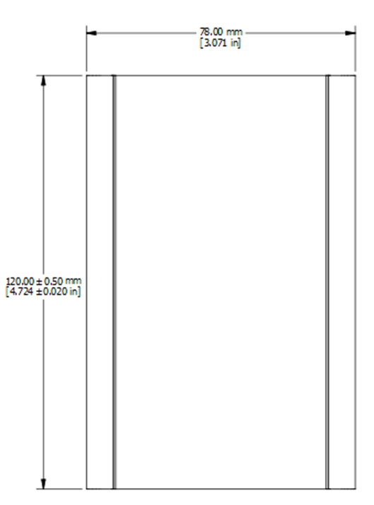
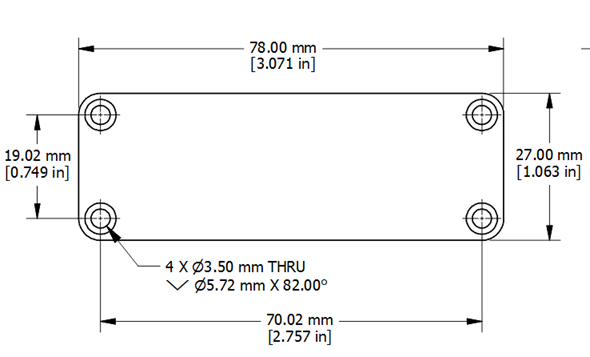
Dimensional Drawing