GECO Series
Product Introduction
Graphical Embedded Controller (GECO) is a modular, high-performance embedded industrial controller specifically designed for industrial automation, machine vision, and precise motion control.
Centered around NI Single-Board RIO (sbRIO), GECO integrates FPGA and Real-Time (RT) processors, supporting graphical programming with LabVIEW. This hardware-software integration allows engineers to rapidly develop high-reliability, high-determinism control systems without the complexity of traditional HDL or C-level embedded development.
Core Features
High Determinism and Performance
- FPGA Technology: Features high-performance FPGA for nanosecond-level logic execution, high-speed signal processing, and customizable high-speed I/O.
- Real-Time Processor: Equipped with a Real-Time OS (NI Linux Real-Time), ensuring deterministic execution of control loops and reliable data logging.
Modular Expansion
- Rich I/O Modules: Supports dozens of GECO expansion modules, including AI, AO, DI, DO, Motion Control, Serial Communication, and specialized sensor modules.
- Flexible Combination: Users can freely combine modules through a backplane or breakout boards to adapt to different application requirements.
Graphical Development
- LabVIEW Integration: Fully compatible with NI LabVIEW and LabVIEW Real-Time/FPGA modules.
- WPC SDK: Provides specialized VIs to simplify hardware configuration and common industrial protocol communication.
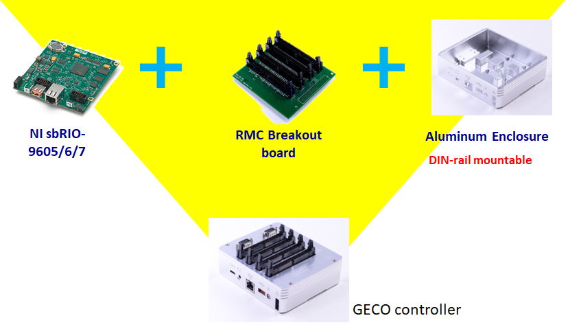
System Architecture
The GECO ecosystem consists of three main components:
- Controller Board: Core processing unit (sbRIO-9606/9607).
- Breakout/Backplane Board: Interfaces the controller with expansion modules.
- GECO Modules: Modular units for specific signal processing or control functions.
Supported SDKs
| SDK | Description |
|---|---|
| LabVIEW | Native support for graphical programming and FPGA. |
| C/C++ | Support via NI Linux Real-Time cross-compilation. |
| Python | Supported for high-level management and data processing via WPC Python Driver. |