WPC sbRIO RMC Breakout Board
WPC has specifically designed the RMC (RIO Mezzanine Card) Breakout Board for the NI sbRIO series to address the challenges hardware developers face when handling high-density FPGA I/O, facilitating easier and faster integration and development of hardware systems.
1. What is the RMC (RIO Mezzanine Card) Interface?
NI sbRIO (Single-Board RIO) is a powerful embedded controller. To maintain maximum flexibility, sbRIO integrates a vast number of FPGA I/O (up to 96 3.3V digital I/O channels) and high-speed processor signals into a single high-density expansion connector known as the RMC (RIO Mezzanine Card).
Users can utilize this RMC connector to design and customize their own peripheral boards (Mezzanine Cards), thereby maximizing the performance of sbRIO.
2. Why is the WPC RMC Breakout Needed?
While the RMC interface offers high freedom, designing and producing a custom RMC expansion board is a significant challenge for most users and small-to-medium development teams:
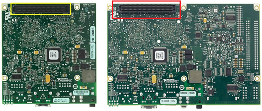
2.1 Difficult BGA Packaging
The RMC connector used by sbRIO is a high-density BGA (Ball Grid Array) package or a similar fine-pitch mezzanine connector. These connectors cannot be hand-soldered, and procurement is difficult, often with high minimum order quantities (MOQ).
2.2 Strict Process and Yield Requirements
High-speed FPGA I/O circuit boards require rigorous consideration of impedance matching and signal integrity during hardware design. In actual SMT (Surface Mount Technology) production, there are high requirements for stencil thickness, reflow oven temperature profile control, and flux selection. Poor control of production conditions can easily lead to BGA cold joints or internal micro-shorts, resulting in significant yield loss during mass production and substantial cost losses.
2.3 Difficulty in Repair and Replacement
Once a BGA or high-density mezzanine connector is damaged or has poor contact, it is nearly impossible to de-solder and repair manually because the connections are hidden beneath the board. Usually, the entire circuit board must be scrapped.
3. The WPC RMC Breakout Solution
To allow developers to directly enjoy the advantages of Graphical System Design (GSD) with sbRIO without getting bogged down in low-level hardware development, WPC designed the RMC Breakout board.
The WPC RMC Breakout directly converts the difficult-to-handle sbRIO RMC connector into the most common, easiest to process, and pluggable standard interfaces in industrial testing and automation (such as IDC headers or D-Sub connectors).
Core Advantages:
- Plug and Play: Eliminates the risk of designing BGA circuit boards, allowing immediate start of software development and verification.
- High Reliability: WPC has ensured the impedance and production yield of the breakout board, providing a guarantee for stable operation.
- Flexible Expansion: Not only does it lead out the original DIO, but some models also integrate RS-232, CAN, or even a second Ethernet chip, expanding sbRIO's native communication capabilities.
4. WPC RMC Breakout Series
WPC currently provides three different types of RMC Breakout boards:
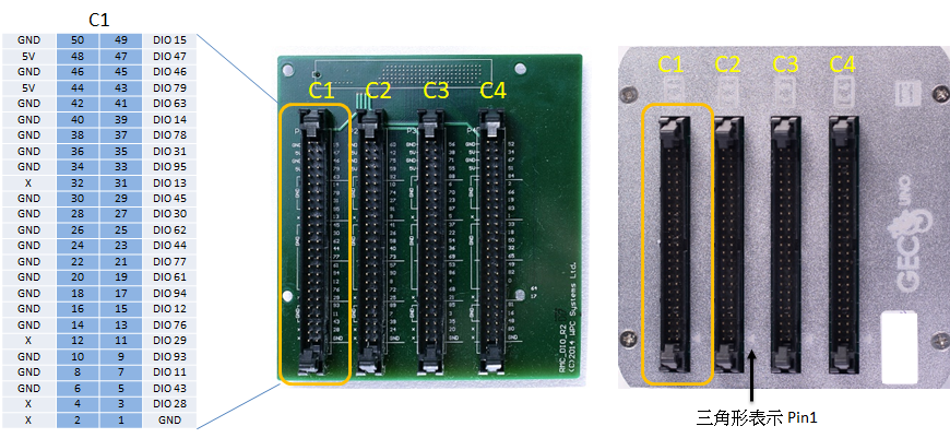
4.1 RMC-BK (Supports UNO Enclosure)
The most basic breakout model, suitable for the entire sbRIO series and perfectly compatible with the GECO UNO controller enclosure. This breakout board simply distributes and leads out the 96-pin 3.3V FPGA DIO.
- Splits the 96-pin DIO into 4 Slots.
- Each Slot contains 24-pin DIO and leads out 5V power for external use.
- Direct point-to-point connection to the FPGA chip (no extra opto-isolation).
- Built-in RTC (Real-Time Clock) backup battery socket.
4.2 RMC-BK-SERIAL (Does Not Support Enclosure)
Designed specifically for applications requiring additional communication interfaces beyond basic DIO expansion. This board is wider and does not support the standard UNO enclosure.
- Also splits the 96-pin DIO into 4 Slots (each with 24-pin DIO and 5V power output).
- Direct connection to the FPGA chip (no isolation).
- Highlight: Built-in converter chips, directly supporting RS-232 / CAN communication breakout.
- Built-in RTC backup battery socket.
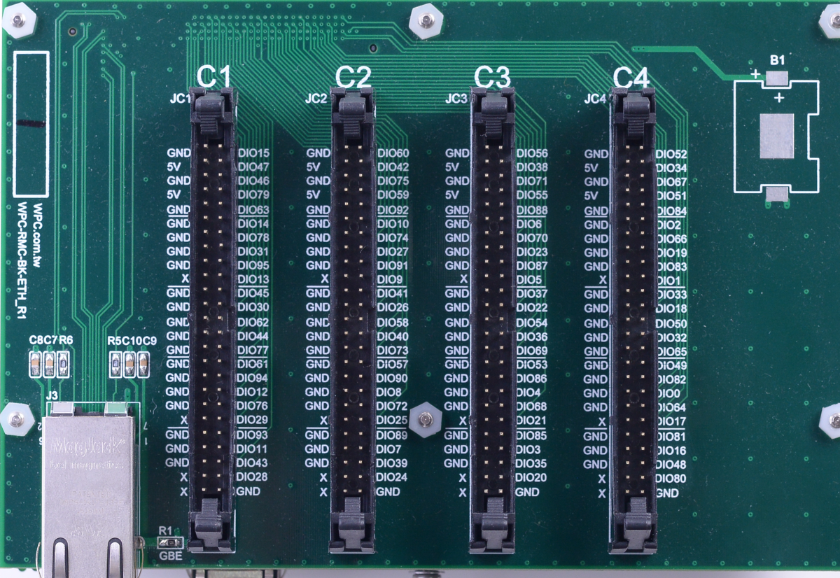
4.3 RMC-BK-ETH (Does Not Support Enclosure)
Born for applications requiring higher network bandwidth or dual-network segment isolation. This board is also wider and does not support the standard UNO enclosure.
- Also splits the 96-pin DIO into 4 Slots.
- Direct connection to the FPGA chip (no isolation).
- Highlight: Built-in Ethernet controller chip, supporting a 2nd Gigabit Ethernet RJ-45 port.
- Built-in RTC backup battery socket.
5. Connector Pinouts
If users need to customize LabVIEW FPGA programs or design peripheral circuits to interface with the board, please refer to the following connector pinouts for the breakout board. (Note: If only using the standard GECO driver provided by WPC, direct control of these low-level pins is not necessary)
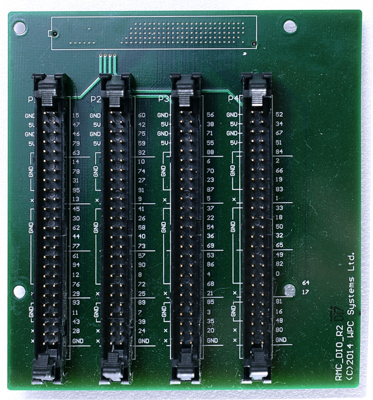
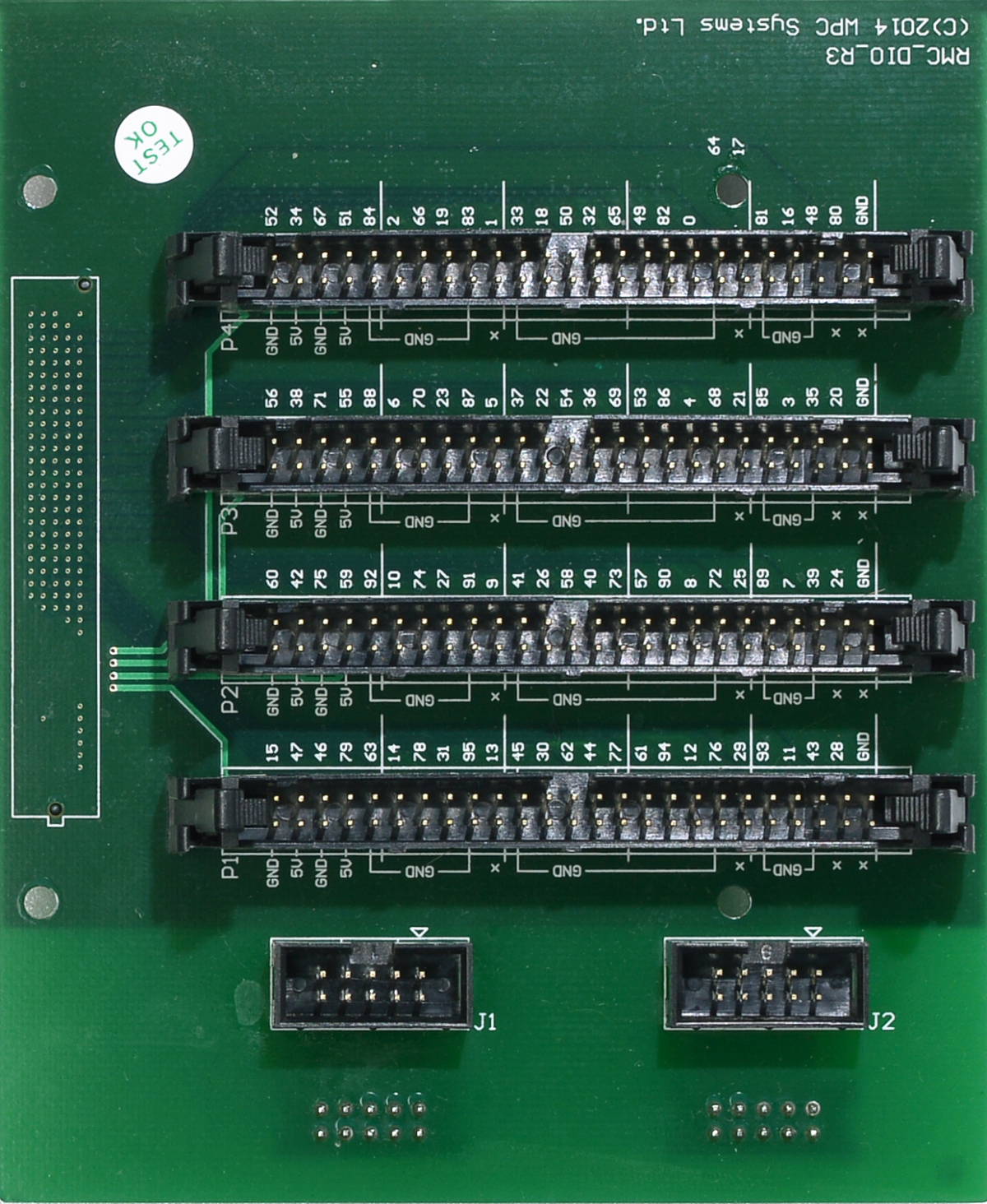
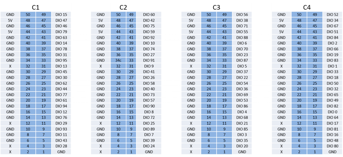
5.1 IDC-50P Pinouts
This interface is the IDC 50-pin header definition used by the 4 Slots.
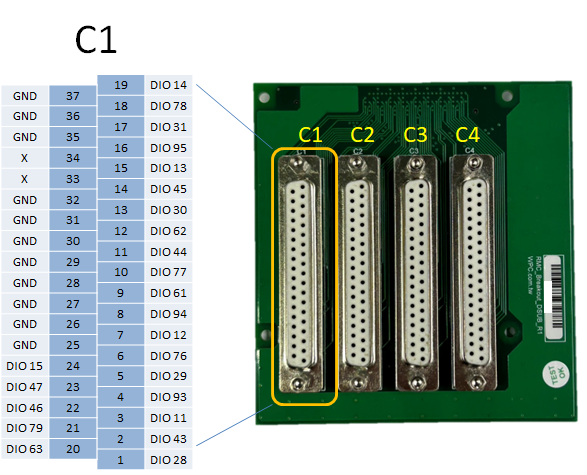
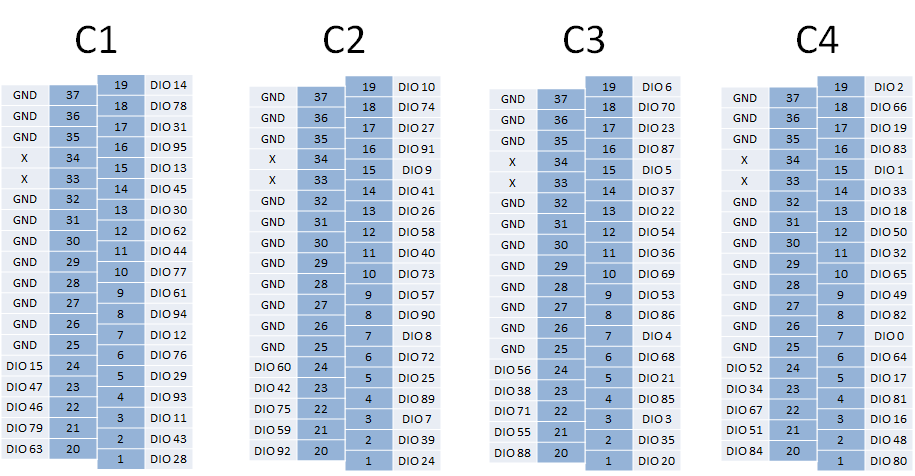
5.2 DSUB-37P Pinouts
Definition of the DSUB 37-pin connector used for some special breakouts or communication interfaces.