Appearance and LED Status
Hardware Appearance
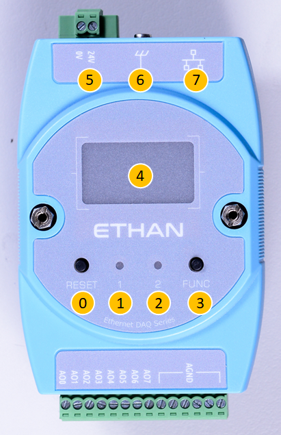
Interface Description by Number
The following table corresponds to the numbers in the figure above, describing the hardware interface functions of the Ethan series products:
| No. | Component Name | Function Description |
|---|---|---|
| 0 | Reset Button | 1. Restart: Press directly to restart the device. 2. Bootloader Mode: Press and hold the FUNC button and the reset button at the same time, the device will restart and enter Bootloader mode. |
| 1 | LED1 Status Indicator | Displays the operating status of the system main program (see LED Status for details). |
| 2 | LED2 OS Indicator | Displays the operating system and network connection status (see LED Status for details). |
| 3 | FUNC Button | 1. Reset IP: Long press for about 3 seconds to reset the IP to the default 192.168.1.110.2. Switch Display: Short press to switch OLED panel display pages. |
| 4 | OLED Panel | Displays network settings information, firmware version, serial number, and other system statuses. |
| 5 | 24V DC Power Input | Power supply interface, input voltage is 24V DC. |
| 6 | Protective Earth (PE) | Ground terminal to ensure equipment safety and noise immunity. |
| 7 | Ethernet Port | 10/100M Ethernet interface for data transfer and communication. |
LED Indicator Status
LED1: System Status
| LED Behavior | Status Description |
|---|---|
| Blinks on startup | Main program initialization normal (blinks twice) |
| Solid on | System operation normal |
| Periodic blinking | Error occurred |
LED2: OS Status
| LED Behavior | Status Description |
|---|---|
| Blinks on startup | Bootloader initialization normal (blinks twice) |
| Solid on | Bootloader running |
| Periodic blinking | OS operating normally |
| Frequency 4 Hz | Ethernet cable connected |
| Frequency 2 Hz | Ethernet cable not connected |
| Off | OS stopped |