EDrive-ST
Product Introduction
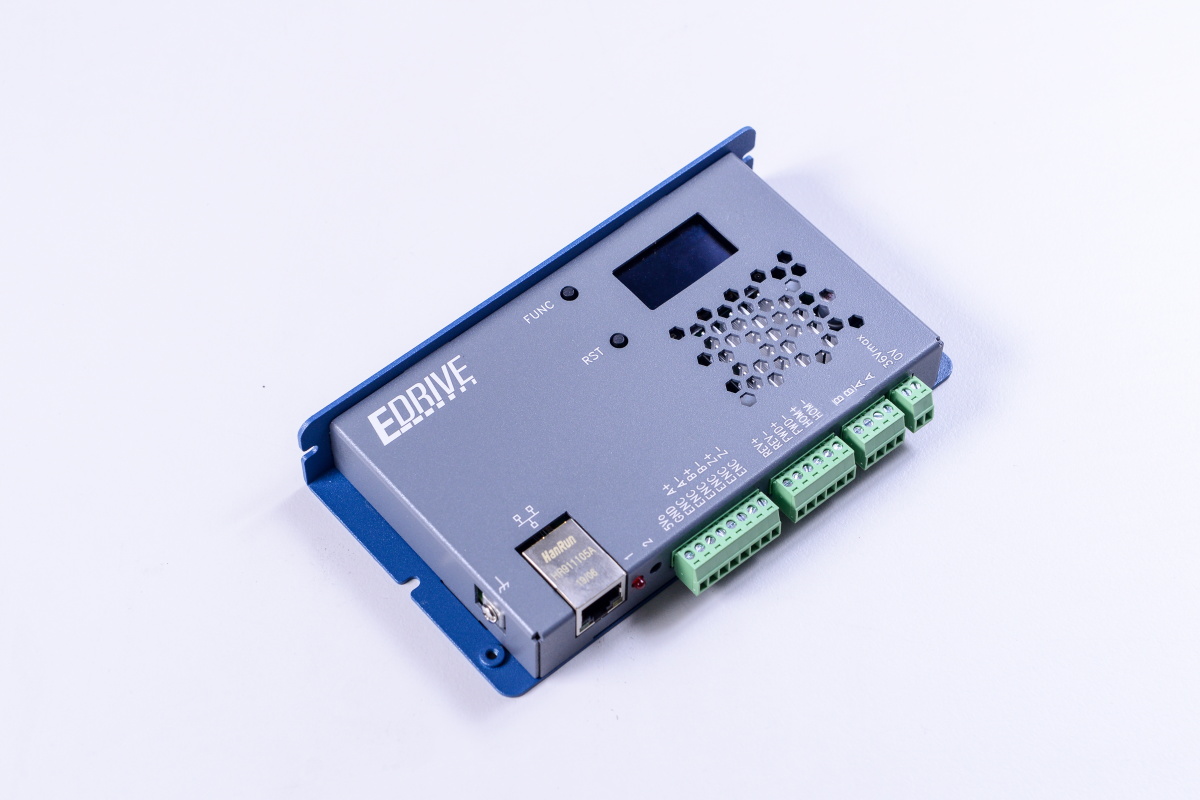
WPC EDrive-ST is a single-axis stepper motor integrated driver equipped with a network interface. It can directly connect to two-phase stepper motors, incremental encoders, and limit switches. No additional axis cards are required; control can be achieved with just a computer and an Ethernet cable.
Compact in size and simple to wire, it is widely used in semiconductor equipment, small laboratory setups, and scientific research instruments. Powered by DC power, it supports up to 36V, making it suitable for DC environments like mobile vehicles, solar photovoltaics, and energy storage systems.
Core Features
| Feature | Description |
|---|---|
| Integrated Design | Built-in driver and network control interface, no extra axis card needed |
| Flexible Control | Supports position control and velocity control modes |
| High-Res Microstepping | Up to 51200 steps/rev (adjustable) |
| Rich I/O | Supports ABZ differential encoder, Home / FWD / REV limit switches |
| Intelligent Functions | Stall detection, smart energy saving, and driver diagnostics |
| Multi-language SDKs | Supports Python, C#, and LabVIEW |
System Architecture Diagram
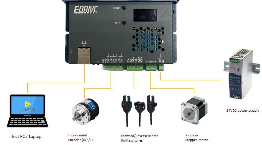
EDrive-ST only supports two-phase stepper motors.
Main Specifications
| Item | Description |
|---|---|
| Power Input | 24VDC (supports up to 36V) |
| Network Interface | 10/100 T-based Ethernet |
| Motor Type | 2-phase stepper motor |
| Microstep Resolution | 51200 steps/rev (adjustable) |
| Max Output Current | 2.1A (5A peak) |
| Encoder | ABZ Incremental (8MHz nominal) |
| Limit Switch Input | Home / FWD / REV |
| Other Functions | Stall detection / Smart energy saving / Diagnostics |
| Accel/Decel Curve | 8-segment ramp smooth acceleration |
| Supported SDKs | Python, C#, LabVIEW |
Appearance
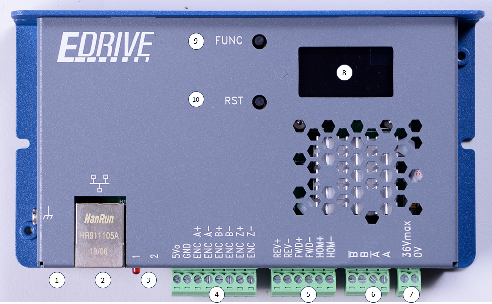
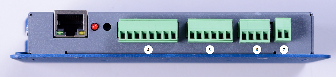
The following table corresponds to the numbers in the figure above and describes the hardware interface functions of EDrive-ST:
| Number | Component Name | Function Description |
|---|---|---|
| 1 | Protective earth (PE) | Ground terminal to ensure equipment safety and noise immunity. |
| 2 | Ethernet Port | 10/100M Ethernet interface for data transfer and communication. |
| 3 | LED1 Status Indicator / LED2 OS Indicator | Display system main program operation status and operating system status (see LED Status for details). |
| 4 | Encoder IO (Differential / RSE) | Encoder input interface, supporting differential and single-ended encoders. |
| 5 | Limit switches | Limit switch input interface, supporting Home / FWD / REV three limit switches. |
| 6 | Stepper motor (2-phase only) | 2-phase stepper motor output interface. |
| 7 | 24V DC Power Input | Power supply interface, input voltage is 24V DC. |
| 8 | OLED Panel | Displays network settings information, firmware version, serial number, and other system statuses. |
| 9 | FUNC Button | 1. Reset IP: Long press for about 3 seconds to reset the IP to the default value 192.168.1.110.2. Switch Display: Short press to switch the OLED panel display page. |
| 10 | Reset Button | 1. Restart: Press directly to restart the device. 2. Bootloader Mode: Press and hold the FUNC button and the reset button at the same time, the device will restart and enter Bootloader mode. |
LED Indicator Status
LED1: System Status
| LED Behavior | Status Description |
|---|---|
| Blinks on startup | Main program initialization normal (blinks twice) |
| Solid on | System operation normal |
| Periodic blinking | Error occurred |
LED2: OS Status
| LED Behavior | Status Description |
|---|---|
| Blinks on startup | Bootloader initialization normal (blinks twice) |
| Solid on | Bootloader running |
| Periodic blinking | OS operating normally |
| Frequency 4 Hz | Ethernet cable connected |
| Frequency 2 Hz | Ethernet cable not connected |
| Off | OS stopped |
Connector 4 — Encoder Input
| Pin | Name | Description |
|---|---|---|
| 1 | 5V (out) | 5V power output for encoder use |
| 2 | GND | Ground |
| 3 | ENC_A+ | Encoder Phase A positive |
| 4 | ENC_A- | Encoder Phase A negative |
| 5 | ENC_B+ | Encoder Phase B positive |
| 6 | ENC_B- | Encoder Phase B negative |
| 7 | ENC_Z+ | Encoder Phase Z positive |
| 8 | ENC_Z- | Encoder Phase Z negative |
Pin 1 provides 5V power and Pin 2 is Ground, which can be used directly to power the encoder.
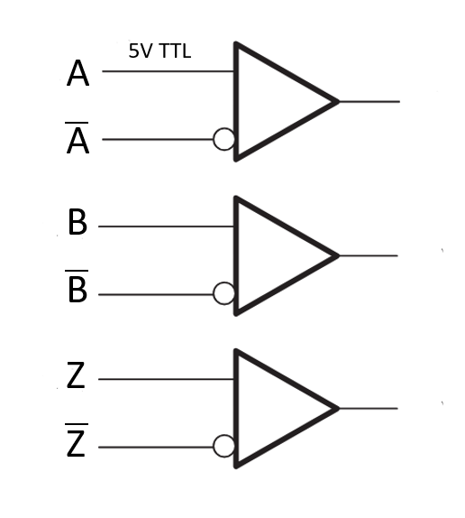
Differential Encoder
Differential encoders are supported by default, with 5V TTL voltage levels.
Single-ended Encoder
Connect the encoder outputs to the ENC_A/B/C+ terminals, leaving the ENC_A/B/C- terminals floating.

If you need to use a single-ended encoder, please inform WPC or your distribution partner before shipment.
Connector 5 — Limit Switch Input
| Pin | Name | Description |
|---|---|---|
| 1 | LIM_REV+ | Reverse limit positive |
| 2 | LIM_REV- | Reverse limit negative |
| 3 | LIM_FWD+ | Forward limit positive |
| 4 | LIM_FWD- | Forward limit negative |
| 5 | LIM_HOM+ | Home switch positive |
| 6 | LIM_HOM- | Home switch negative |
Internal Current Limiting Resistor
A 6.8kΩ current limiting resistor is built-in; no external resistor is required.

NPN Type Limit Switch
Connect LIM_FWD/REV/HOM+ to 24V (common anode), and the limit switch output to LIM_FWD/REV/HOM-.

PNP Type Limit Switch
Connect LIM_FWD/REV/HOM- to 0V (common cathode), and the limit switch output to LIM_FWD/REV/HOM+.

Mechanical Limit Switch
One of the following two wiring methods can be selected:


Connector 6 — Stepper Motor Output
| Pin | Name | Description |
|---|---|---|
| 1 | B\ | Phase B negative |
| 2 | B | Phase B positive |
| 3 | A\ | Phase A negative |
| 4 | A | Phase A positive |
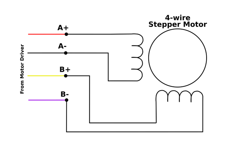
4-Wire Wiring
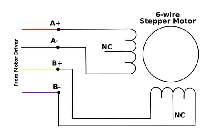
6-Wire Wiring
Do not connect the common terminals in the middle of the coils; only connect the two ends of each coil.
Connector 7 — Power Input
| Pin | Name | Description |
|---|---|---|
| 1 | 24V | DC power positive |
| 2 | 0V | Ground |
The standard input voltage is 24VDC.