EDrive-SRV
Product Introduction
WPC EDrive-SRV is characterized by its small size, simple wiring, and ease of use, making it ideal for system development in semiconductor equipment, small-scale laboratory equipment, and scientific research instruments.
It operates on DC power, supporting up to 48V with a maximum output power of 400W. This makes it suitable for DC-powered environments such as mobile vehicles, solar photovoltaics, energy storage systems, batteries, and battery-powered setups.
info
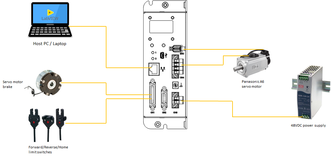
EDrive-SRV currently only supports Panasonic A6 series servo motors.
info
EDrive-SRV operates on DC power, supporting up to 48V.
System Architecture Diagram
Main Specifications
| Item | Description |
|---|---|
| Motor Type | Panasonic A6 Series (AC Servo Motor) |
| Limit Switches | FWD, REV (Home not included) |
| Other I/O | Brake release, Break-point |
| Encoder | 23-bit absolute encoder |
| Power Input | 12~48V DC (Max output power 400W) |
| Supported SDKs | Python, C#, LabVIEW |
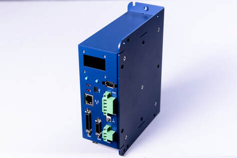
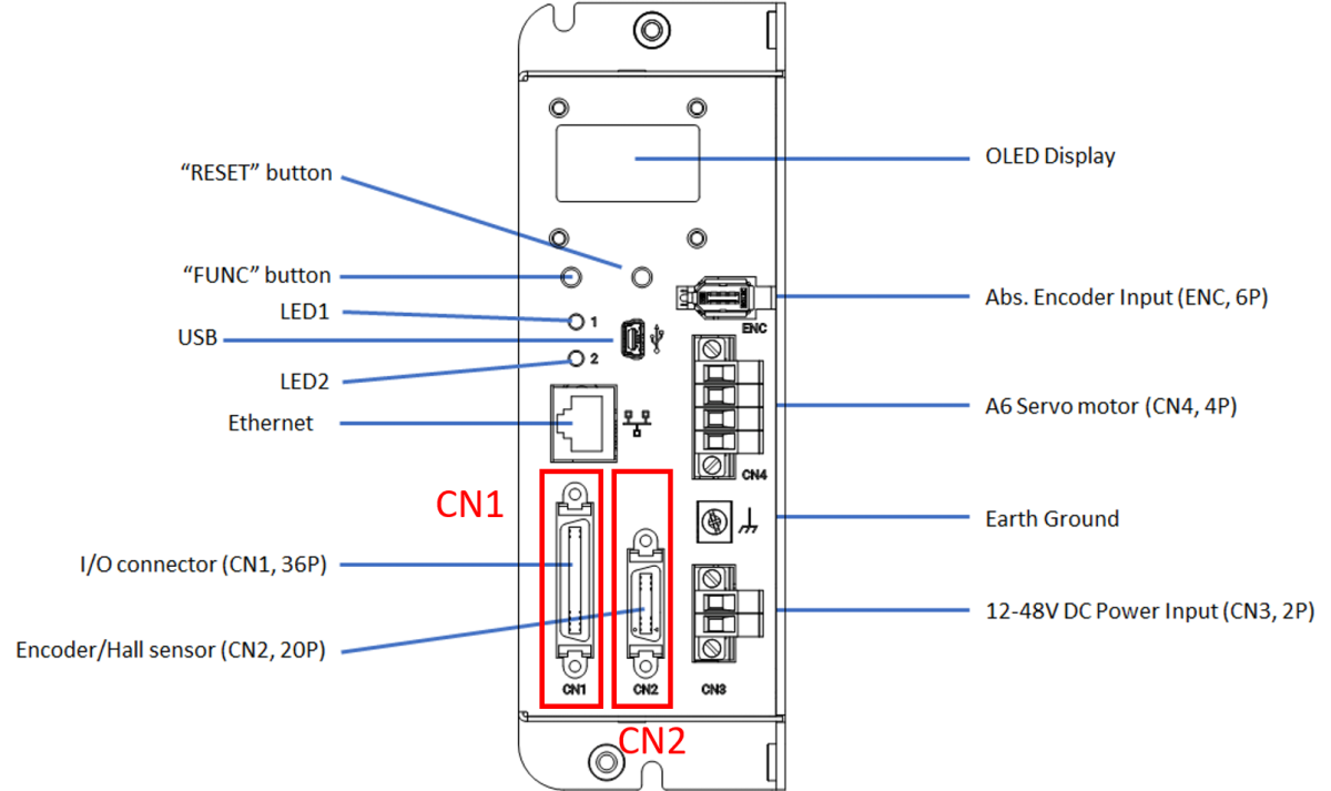
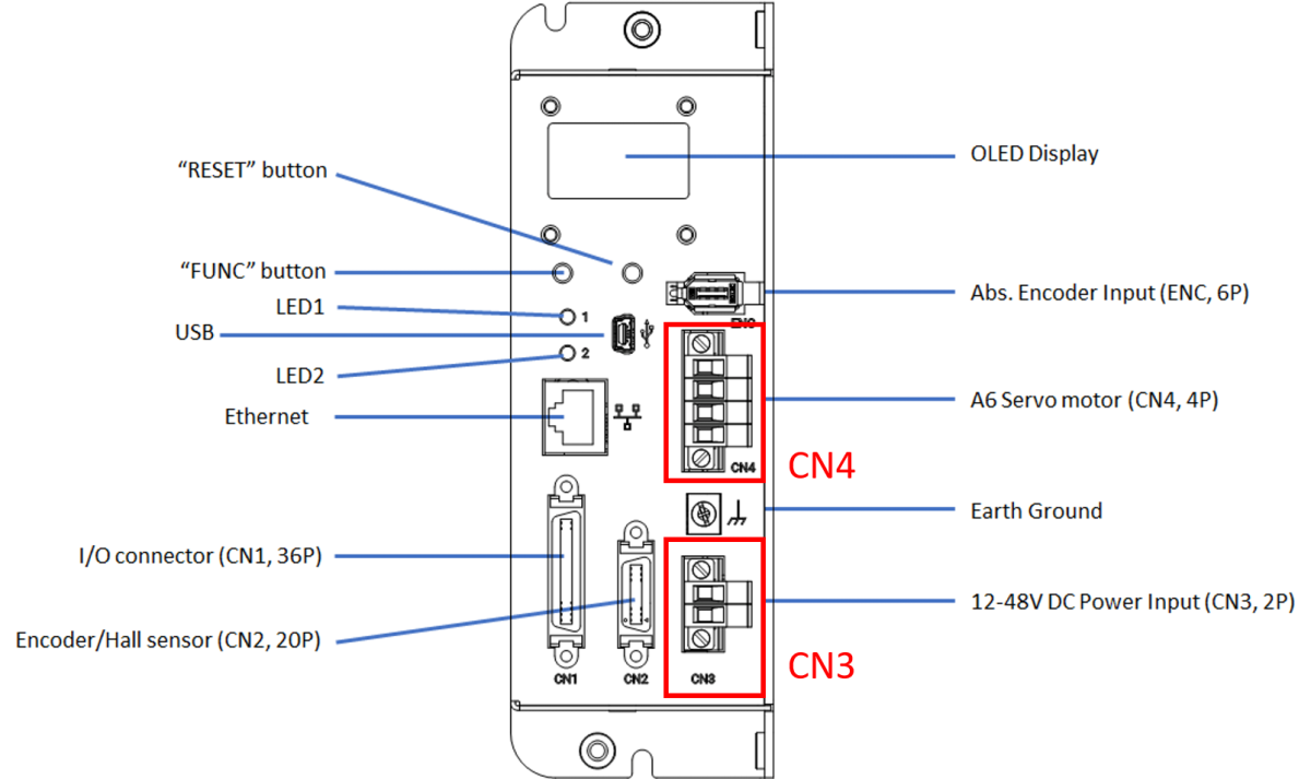
Appearance
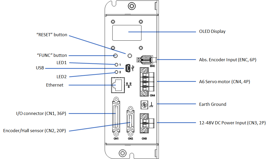
Describing the hardware interface functions of the EDrive-SRV series products:
| No. | Component Name | Function Description |
|---|---|---|
| 1 | Reset Button | 1. Restart: Press directly to restart the device. 2. Bootloader Mode: Press and hold the FUNC button and the reset button at the same time, the device will restart and enter Bootloader mode. |
| 2 | FUNC Button | 1. Reset IP: Long press for about 3 seconds to reset the IP to the default value 192.168.1.110.2. Switch Display: Short press to switch the OLED panel display page. |
| 3 | LED1 Status Indicator | Display system main program operation status (see LED Status for details). |
| 4 | LED2 OS Indicator | Displays the operating system and network connection status (see LED Status for details). |
| 5 | USB Port | Micro-USB Port, used for firmware updates, parameter configuration, and device debugging. |
| 6 | Ethernet Port | 10/100M Ethernet interface for data transfer and communication. |
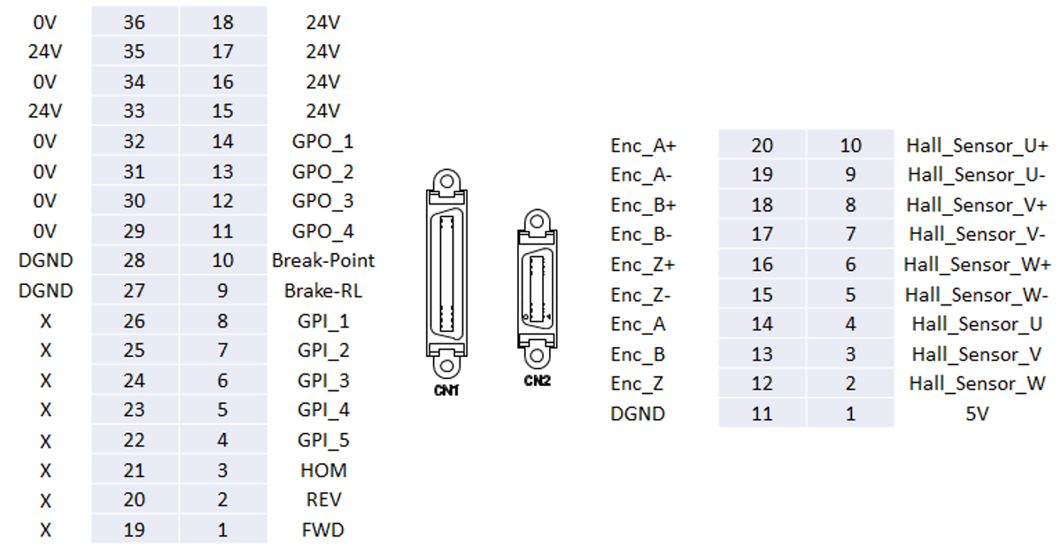
| 7 | I/O connector (CN1, 36P) | Digital I/O interface, including limit switches (FWD/REV), brake release (Brake), and break-point signals. |
| 8 | Encoder/Hall sensor (CN2, 20P) | Motor feedback interface, receiving encoder and Hall sensor signals for dynamic position monitoring and closed-loop control. |
| 9 | OLED Panel | Displays network settings information, firmware version, serial number, and other system statuses. |
| 10 | Abs. Encoder Input(ENC, 6P) | Absolute encoder input, used to read Panasonic 23-bit high-resolution encoder data. |
| 11 | A6 Motor Power Output(CN4, 4P) | Servo motor power output, connected to the power input terminal of Panasonic A6 series servo motors. |
| 12 | Earth Ground | Ground terminal to ensure equipment safety and noise immunity. |
| 13 | 12-48V DC Power Input(CN3, 2P) | Power supply interface, input voltage is 12~48V DC. |
LED Status
LED1: System Status
| LED Behavior | Status Description |
|---|---|
| Blinks on startup | Main program initialization normal (blinks twice) |
| Solid on | System operation normal |
| Periodic blinking | Error occurred |
LED2: OS Status
| LED Behavior | Status Description |
|---|---|
| Blinks on startup | Bootloader initialization normal (blinks twice) |
| Solid on | Bootloader running |
| Periodic blinking | OS operating normally |
| Frequency 4 Hz | Ethernet cable connected |
| Frequency 2 Hz | Ethernet cable not connected |
| Off | OS stopped |
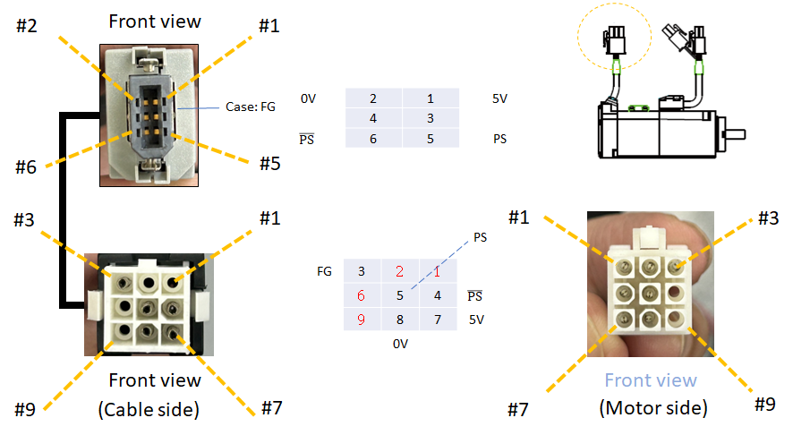
Pinout Definitions
I/O and Encoder Pin Wiring
I/O Connector Wiring Example

Power Pin Wiring
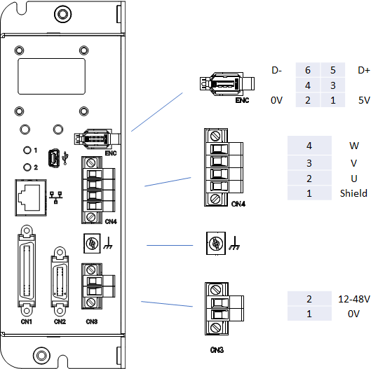
Encoder Pin Wiring